


3 PFAFF
Notes on safety
●The machine must only be operated in full knowledge of the instruction book and by
persons with appropriate training.
●Before commissioning the machine also read the motor manufacturer’s safety notes and
instruction manual.
●The machine must only be used for the purpose intended. It must not be operated without
the safety devices it is equipped with; all valid safety regulations must be adhered to.
●When gauge parts are exchanged (e.g. needle, presser foot, needle plate, feed dog and
bobbin), during threading, when the workplace is left, and during service work, the
machine must be isolated from the mains by switching off the main switch or
disconnecting the mains plug.
●On mechanically operated clutch motors without start inhibitor it is necessary to wait until
the motor has stopped.
●Daily servicing work must only be carried out by persons with appropriate training.
●Repairs and special maintenance work must only be carried out by trained technicians or
persons with appropriate training.
●For service or repair work on pneumatic systems the machine must be disconnected from
the compressed air supply system. The only exceptions to this are adjustments and
function checks carried out by appropriately trained technicians.
●Work on the electrical equipment must only be carried out by electrical engineers or other
appropriately trained technicians.
●It is not permitted to work on live parts. For exceptions please see the EN 50 110
regulations.
●Conversions or changes to the machine must only be made on adherence to all safety
regulations.
●For repairs, only replacement parts approved by us must be used.
●The sewing head must not be operated until it is ascertained that the whole sewing unit
corresponds to EC-regulations.
Tools, gauges and other adjustment aids
●1 set of screwdrivers with blades from 2 to 10 mm wide
●1 set of spanners from 7 to 14 mm wide
●1 set of hexagonal allen keys ranging from 1.5 to 6 mm
●1 wrench, 22 mm wide
●1 metal ruler (part No. 08-880 218-00)
●1 cylindrical pin (5 mm in diameter), part No. 13-030 341-05
●1 adjustment gauge, part No. 61-111 642-19
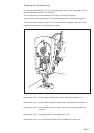
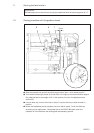
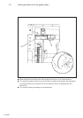
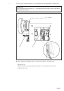
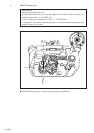
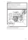
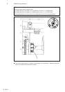
Notes on the service manual
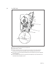
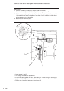
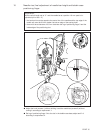
All the adjustments in this service manual apply for a completely mounted machine. No
mention is made of the machine covers that occasionally have to be screwed off and back on
for testing and adjustment purposes.
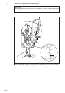
The screws and nuts in brackets ( ) are for the attachment of machine parts that must be
loosened before the adjustments and tightened up again afterwards.
Abbreviations
t.d.c = top dead center
b.d.c. = bottom dead center