


7
Grounding/Bonding
Install, ground, bond and wire motor according to local
or National Electrical Code requirements.
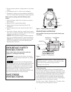
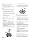
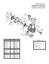
Permanently ground motor. Use green ground terminal
provided under motor canopy or access plate (See Figure
4); use size and type wire required by code. Connect
motor ground terminal to electrical service ground.
Bond motor to pool structure. Use a solid copper conductor,
size No. 8 AWG (8.4 sq.mm) or larger. Run wire from exter-
nal bonding lug (see Figure 4) to reinforcing rod or mesh.
Connect a No. 8 AWG (8.4 sq.mm) solid copper bonding
wire to the pressure wire connector provided on the
motor housing and to all metal parts of the swimming
pool, spa, or hot tub and to all electrical equipment,
metal piping or conduit within 5 feet (1.5 m) of the inside
walls of swimming pool, spa, or hot tub.
Wiring
NOTICE: 3 phase models require magnetic motor starters
and external overload protection. If in doubt about the
procedure, consult a licensed electrician.
Pump must be permanently connected to circuit. Table I,
Page 8, give correct wire and circuit breaker sizes for the
pump alone. If other lights or appliances are also on the
same circuit, be sure to add their amp loads to pump
amp load before figuring wire and circuit breaker sizes.
(If unsure how to do this or if this is confusing, consult a
licensed electrician.) Use the load circuit breaker as the
master on-off switch.
Install a Ground Fault Circuit Interrupter (GFCI) in circuit;
it will sense a short-circuit to ground and disconnect
power before it becomes dangerous to pool users. For
size of GFCI required and test procedures for GFCI, see
manufacturer’s instruction.
In case of power outage, check GFCI for tripping (which
will prevent normal pump operation). Reset if necessary.
NOTICE: If you do not use conduit when wiring motor,
be sure to seal wire opening on end of motor to prevent
dirt, bugs, etc., from entering.
Risk of dangerous or fatal electrical shock.
Be sure that power to the motor circuit is off before
working on wiring, wiring connections, or motor. Re-in-
stall the motor end cover and all other wiring covers be-
fore turning on the power.
1. Turn off power.
2. Remove the motor end cover.
To Wire a Single Speed, Single Voltage Motor
There are two terminals labeled L1 and L2. Attach the
power leads to these terminals. Either wire may attach to
either terminal.
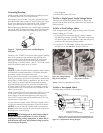
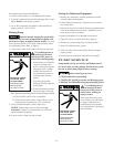
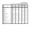
To Wire a Dual-Voltage Motor
Dual voltage motors have a plug to change from 230 volts
(factory setting) to 115 volts.
1. If you have 230 volts motor supply voltage, confirm
that the plug is set for 230 volts. The arrow on the plug
will point to the 230 volt position. Note that plug only
connects with one prong in this position.
2. If you have 115 volt supply, pull the plug straight up
and place it on the two brass prongs as shown.
NOTE: Arrow is highlighted for clarity.
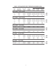
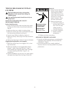
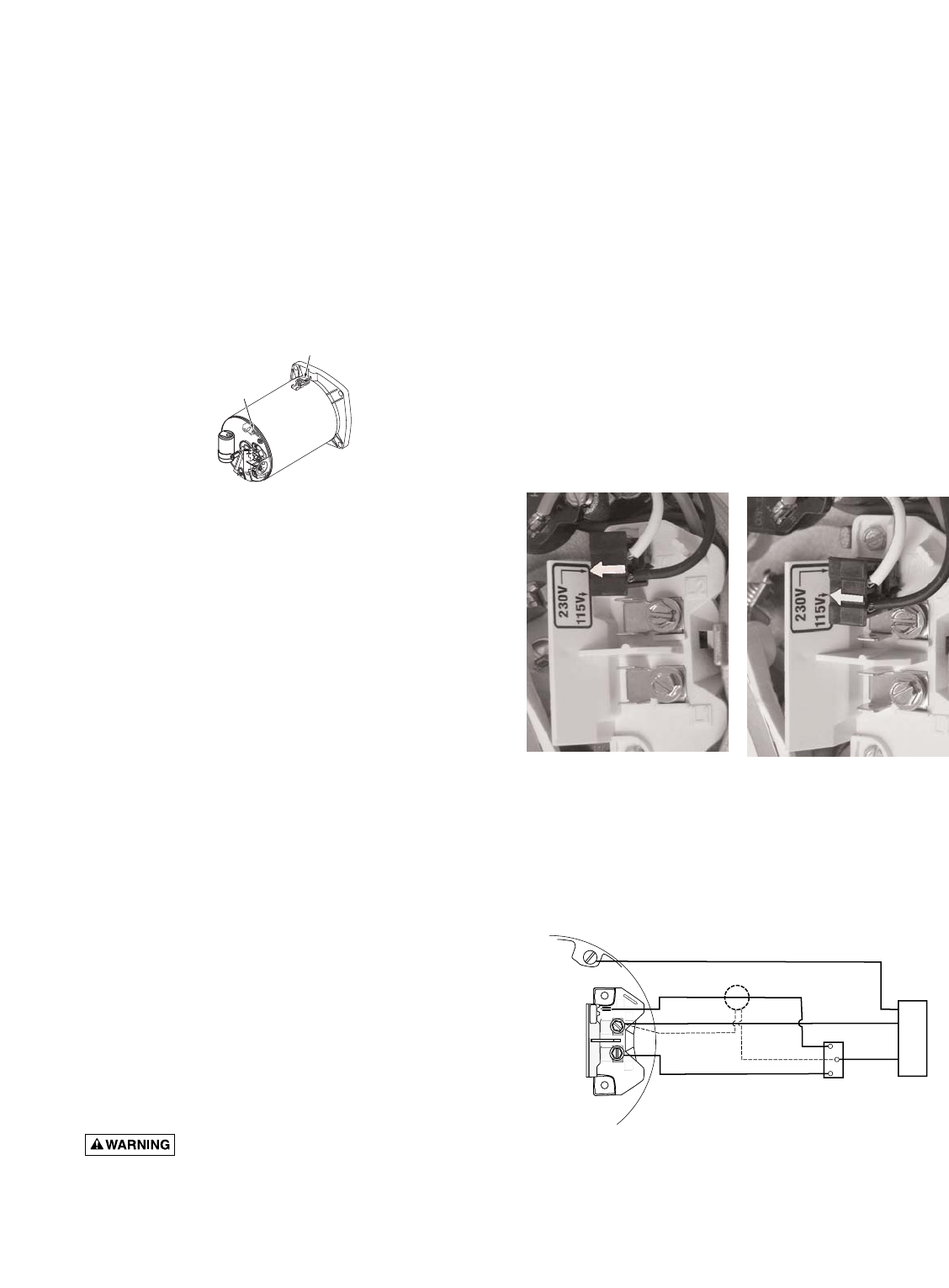
To Wire a Two-Speed Motor
Wire the pump as shown in the diagram.
A
A
L2
L2
L1
L1
230V
115V
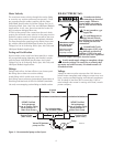
Bonding
Lug
Green
Ground
Screw
Figure 4 – Typical ground screw and bonding lug
locations.
Figure 5B -Voltage Change
Plug Set for 115 Volts
Figure 5A -Voltage Change
Plug Set for 230 Volts
Figure 5C: 2-Speed Motor Wiring Diagram
L2=COM
L1=HI
A=LOW
A
L2
L1
Power Supply for
Optional Timer.
Low Speed
High Speed
Circuit
Protector
Remote
SPDT
Switch
Ground (Green)
Common
If using timer, Connect
Timer Motor to Low Speed Only
Minimum switch and timer amp rating must equal Branch Fuse
Rating given in "Recommended Fusing and Wiring Data" table.
230
Volt
Lines
Back of
motor
with
Terminal
Board
4558 0304