


Pelco Manual C580M Rev D (9/97) 3
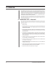
3.0 INSTALLATION
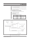
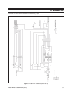
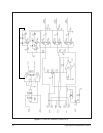
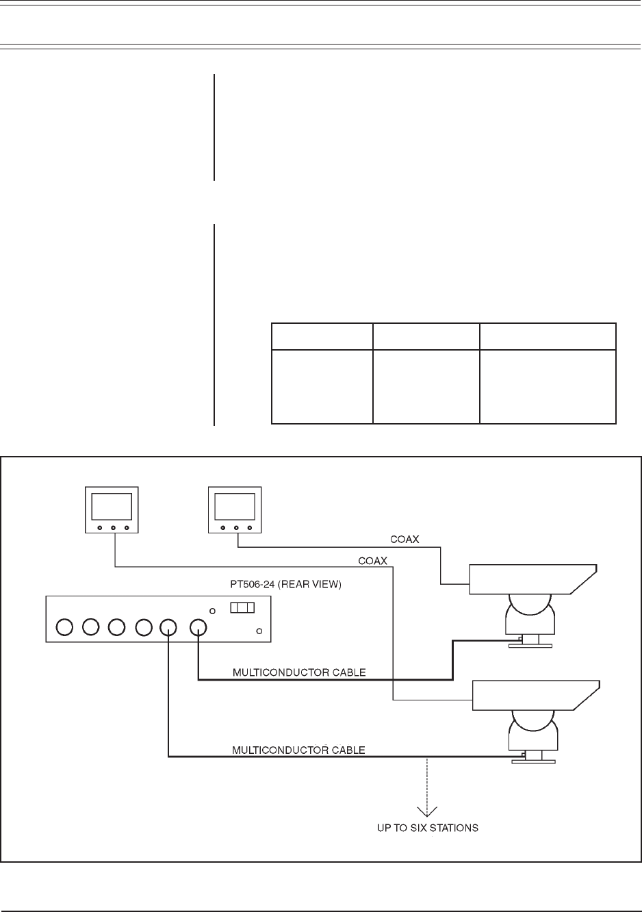
Figure 1 shows a typical rear panel installation of the PT506-24DT controller. The
distance from the controller is limited by the wire size and pan/tilt used. (See Sec-
tion 3.1 Recommended Cable Distances.)
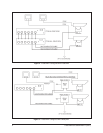
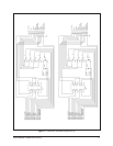
Figure 2 shows a typical rear panel installation of the PT506-24A to the PT506-24DT.
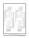
Figure 3 shows a typical system using a relay box to extend the pan/tilt control
range and operate a 120 VAC pan/tilt.
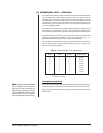
3.1 RECOMMENDED CABLE DISTANCES
The following typical values are based on the conditions as follows:
Single common conductor for the lens
Single common conductor for the pan/tilt
Maximum rated load
10% voltage reduction from line loss
Simultaneous pan/tilt activation (2 amp current draw)
Wire Size Pan/Tilt Lens Functions
22 Awg 40 ft (10 m) 620 ft (182 m)
20 Awg 60 ft (18 m) 1,000 ft (294 m)
18 Awg 95 ft (30 m) 2,300 ft (676 m)
16 Awg 150 ft (45 m) 3,600 ft (1,058 m)
Figure 1. PT506-24DT Basic System Configuration