


Pelco Manual C545M-E (2/02) 5
INSTALLATION
The following items are supplied:
• MPS5DT, MPS524DT, or MPS524DT/220
•6-pin mating connector with pins
•2 screws
CONNECTOR ASSEMBLY
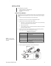
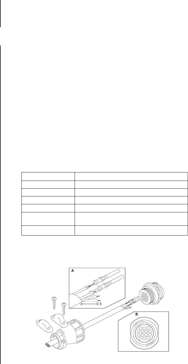
The first thing you must do is assemble the mating connector. The following steps apply to
all AMP style connectors regardless of pin size or pin number. Refer to Figure 1 during as-
sembly.
1. Slide the connector clamp assembly over the conductor cable.
2. Determine the size of wire to use. Refer to the
Specifications
section.
3. Prepare the wires from the conductor cable as follows:
a. Strip at least 1" from the cable jacket to expose the wires. You may need to strip
more from the cable jacket if you have more wires.
b. Strip 1/8" from each wire.
c. Using an AMP-style crimper, crimp the wires and their insulation to the connector
pins. Refer to Detail A in Figure 1.
4. Slide the connector pins into the appropriate holes in the connector body until they
snap into place. You can see the pin assignments in Table A.
Table A. PIN Assignments
PIN FUNCTION
1 Common/AC Low
2 Right
3 Left
4 Auto
5 120 VAC HI for PS20 scanner and camera power or
24 VAC HI for PS20-24 scanner and camera power
8 Chassis Ground
5. Push the connector clamp assembly towards the connector body and screw it onto the
connector body. Be careful not to disturb the wires.
6. Attach the appropriate clamp with the screws provided and tighten.
OR
00103
1"
1/8"
FRONT VIEW
13
47
811
1214
Figure 1. Connector Assembly
NOTE:
Pin 5 is not used
with PS7 and PS30 Series
Scanners.