


4 Pelco Manual C616M-B (11/97)
3.0 INSTALLATION
Systems involving video motion detectors must use the best possible connection
and grounding practices. Poor wiring not only causes poor pictures, but could af-
fect the alert function. Camera and lens selection, camera location, scene lighting,
and mounting are also significant factors in achieving optimum performance. These
factors are covered in more detail in Section 4.5, SYSTEM CONSIDERATIONS.
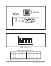
3.1 VIDEO INPUT
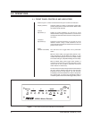
Connect a good grade of coax cable from the camera to the “VIDEO IN” BNC
connector on the rear panel of the MD2001. The MD2001 has a passive loop-
through input. It does not terminate the input in 75 ohms.
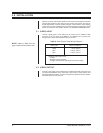
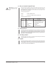
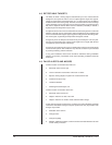
Table A. Video Coaxial Cable Wiring Distances
Cable Type* Maximum Distance
RG59 750 ft (229 m)
RG6 1,000 ft (305 m)
RG11 1,500 ft (457 m)
*Minimum cable requirements:
75 ohms
All-copper center conductor
All-copper braided shield with 95-percent braid coverage
3.2 VIDEO OUTPUT
Connect a good grade of coax cable from the “VIDEO OUT” BNC connector on the
rear panel of the MD2001 to the video input of the monitor or video switcher. This
cable should be terminated in 75 ohms, or if looped through the monitor or switcher,
terminated at the far end of the run.
NOTE:
Refer to Table A for the
type of video coaxial cable to use.