


C3416M-B (11/06) 5
4. Attach the back box to the mounting surface.
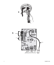
5. Connect wiring to the circuit board inside the back box. When finished, close the door to the back box and turn on the
power. The green LED will light.
NOTES:
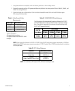
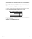
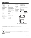
• Aux 1: Maximum 2 A at low voltage (<40 V)
Aux 2: Maximum 30 mA at 32 VDC
• If you are using both unshielded twisted pair (UTP) wiring and a translator board, install the UTP wiring before
installing the translator board.
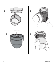
WARNING: An electrical short in the back box may occur if the metal BNC connector is not completely covered by
the protective boot.