


8 C1506M-A (8/02)
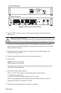
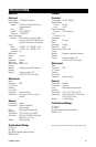
IRD2024 WIRING
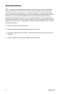
1. Connect power to the 24 VAC INPUT connector on the rear of the receiver. The receiver’s power
requirement is a maximum of 5 VA, not including the camera and pan/tilt. Refer to the pan/tilt
manual for its power requirements. Do not turn on power.
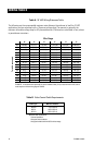
If necessary, refer to Table A in the
Wiring Tables
section to determine appropriate wire sizes
for 24 VAC applications.
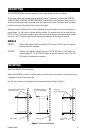
2. Make sure the P/T SELECT switch on the rear of the receiver is set toward 24 VAC. The 115/
230 VAC switch position is used only with the ERD2200.
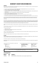
3. Connect the pan/tilt controls (up, down, left, right, and common).
4. Connect the camera power (24 VAC).
5. Connect the motorized lens controls (iris, focus, zoom, and common).
6. Connect video.
VIDEO IN comes from the camera.
VIDEO OUT goes to the controller.
If necessary, refer to Table B in the
Wiring Tables
section to determine appropriate coaxial
cable types for video applications.
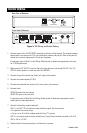
7. Connect the auxiliary outputs (optional).
AUX 1 is a 5 VDC, 20 mA maximum, open collector output. Use the auxiliary:
• To operate low current relays
• To turn on or off a Pelco window wiper that has TTL circuitry
AUX 2 is a normally open/normally closed (Form C) relay. Relay contacts are rated at 1A at 24
VDC or .5A at 115 VAC.
8. Double check all wiring connections, and then turn on power.
A
C
A
C
24V 50/60HZ
INPUT POWER
~
24V
~
50/60HZ
P/T
POWER SELECT
115/230V
~
50/60HZ
A
C
A
C
ERD OPTION
TLC
OUT
VIDEO
IN
PWR
CX
LENS AUX1 AUX2
C N N
OC
24V ,1A
~
I F Z C
CAM PWR
C C
PAN/TILT
5V
CLASS 2 WIRING
ERD OPTIONS
115/230V
50/60Hz
.60 / .27 AMPS
~
IRD 24V
50/60Hz
1.35 AMPS
~
Rear View of Receiver
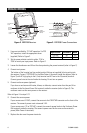
Front View of Receiver
Figure 5. IRD Wiring and Switch Setting