


Pelco Manual C1458SM-A (10/98) 15
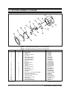
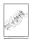
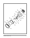
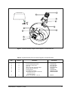
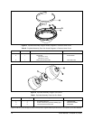
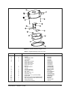
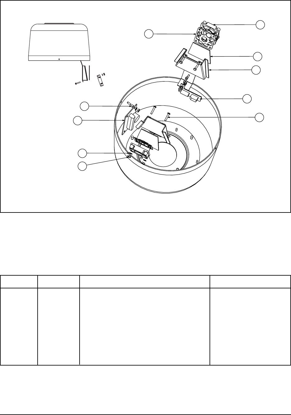
Figure 7. Exploded Assembly Diagram–Heater Segment in Pendant Back Box
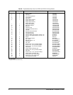
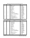
Table G. Exploded Assembly Parts List–Heater Segment in Pendant Back Box
Item Quantity Description Part Number
1 2 Fan, 1 W, 12VDC 70610013
2 2 Fan shroud and heater bracket 7064035COMP
3 2 Heater pad, 15 W, 24 VAC HT01-0321-0202
4 7 Nut, 4-40 ZH4-40NUTSH
5 4 Screw, 4-40 x 5/8", pan head, Phillips ZH4-40X.625SPP
6 7 Internal tooth lock washer, #4 ZH4LWSIS
7 2 Fan finger guard 7064002COMP
8 1 Fan rectifier circuit board PCB9000277ASSY
9 1 Thermostat/terminal block circuit board PCB9000300ASSY
On at 70° F (21° C)
Off at 85° F (29° C)
10 2 Spacer, 3/16" diameter x .125", #4 SPA9015
1
2
3
4
5
6
7
8
9
10