


4 C2494M (12/05)
4
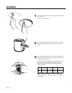
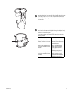
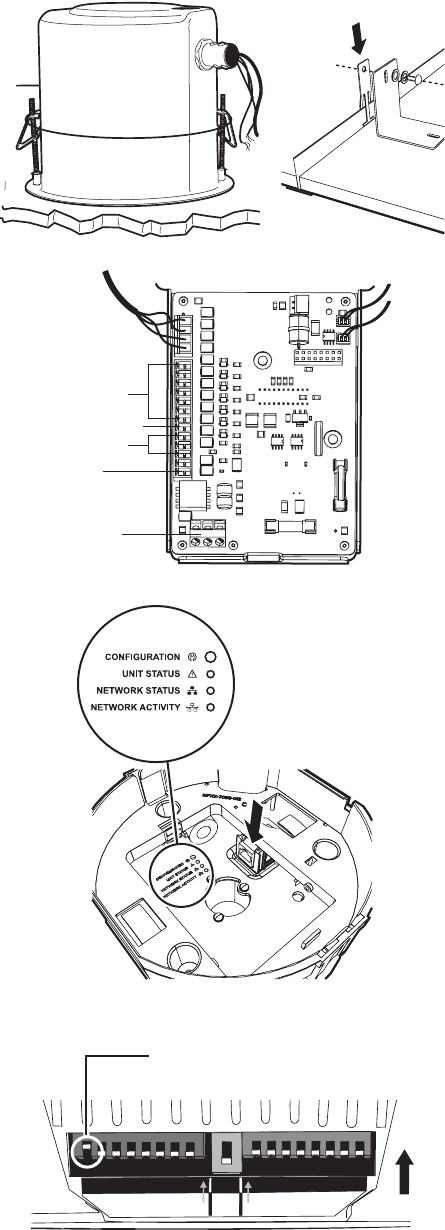
Install the back box by compressing the spring clips and pushing the
back box through the hole. Tighten the screws until you hear a clicking
noise.
Suspended Ceiling Only: Install the ceiling tile with the back box.
Attach a T-rail clip on each side of the ceiling tile to hold the ceiling tile
secure during installation of the dome drive and lower dome.
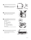
5
Connect the power wires to the circuit board inside the back box.
Connect any alarm and auxiliary circuits. Turn on the power to the
system. The green LED on the door indicates system power is on.
NOTE: Aux 1 – Maximum 2 A at low voltage (<40 V)
6
Connect a 10/100/1000BaseT network Cat5e (or better) cable to the
RJ-45 network connector located inside the back box. Check the LED
indicators located inside the back box to check unit status, network
status, and network activity.
Unit Status LED
Green Unit is functioning normally.
Amber Unit is in configuration mode.
Red Unit is in an error condition.
Network Status LED
Off Unit is not connected to the network.
Amber Unit is connected to a 100BaseT network.
Red Unit is connected to a 10BaseT network.
Network Activity LED
The LED flashes whenever the unit is sending or receiving network data.
7
No DIP switch settings are required for the system. Before installing the
dome drive verify that switch SW1-1 (SW1, switch 1) is set to the ON
position and all other switches are set to the OFF position.
The switches set the dome drive for Pelco’s D protocol, address 1,
2400 baud, and no termination.
ALARMS
ALARM COM
AUX1
AUX COM
POWER
SW1
SW2
SW3
1
2
3
4
5
6
7
8
1
2
3
4
5
6
7
8
1
on on
ON
SW1-1 is set to the ON position.
All other switches are set to the OFF position.