


20 Pelco Manual C1995M-A (10/01)
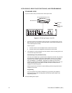
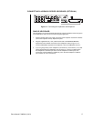
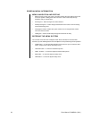
NOTE:
A KBD4000/KBD4002/KBD4000V keyboard cannot be used when a multiplexer is
used with a CM6700 SCU.
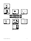
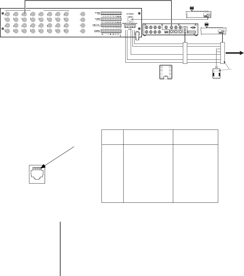
Refer to Figure 4 in the
Applications
section for an overview of a typical application. Refer
to Figure 15 for wiring the multiplexer. Refer to Table B for RJ-45 pin-outs.
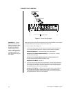
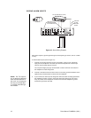
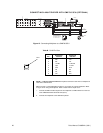
1. Connect the MAIN monitor output from the multiplexer to VIDEO INPUT 5 on the rear
of the CM6700 Switcher/Controller Unit (SCU).
2. Connect the multiplexer to the CM6700 keyboard.
CONNECTING A MULTIPLEXER WITH CM6700 SCU (OPTIONAL)
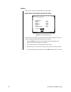
Multiplexer Keyboards
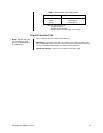
Pin Function Function
1 RX+ TX+
2 RX- TX-
3 12 VDC 12 AC/DC
4 open 12 VAC
5 Gnd Gnd
6NC NC
7 TX- RX-
8 TX+ RX+
PIN 1
Table B. RJ-45 Pin-Outs
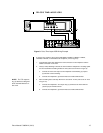
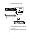
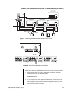
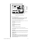
Figure 15. Connecting Multiplexer to a CM6700 SCU
1
2
3
45
6
7
8
R+R-TT+
LOCAL
O
N
O
N
1234
1
2
3
4
5
6
7
8
12 VAC
1
2
3
4
5
6
7
8
O
N
O
N
1234
KBD300
KBD300
MULTIPLEXER
WALL BLOCK
WALL BLOCK
TERMINALS
USER-SUPPLIED CABLE
BETWEEN REMOTE
KEYBOARD PORT AND
ALL WALL BLOCKS
TO
ADDITIONAL
KEYBOARDS
KBDKIT
VIDEO INPUTS
1 3 5 7 9 1 13 15
2 4 6 8 10 12 14 16
VIDEO OUTPUTS
1
2
3
4
ALARMS
COM-IN
COM-OUT
12 VDC
1 2 3 4 H 0
OUT IN
SVHS
VCR
MAIN
SVHS75 OHMS
1234
SPOT
IN
OUT
1234
MULTIPLEXER
CM6700 MATRIX SWITCHER