12 Pelco Installation Manual C1487M-H (1/01)
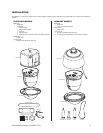
SURFACE-MOUNT INSTALLATION
PENDANT MODELS
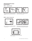
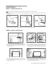
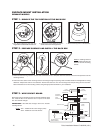
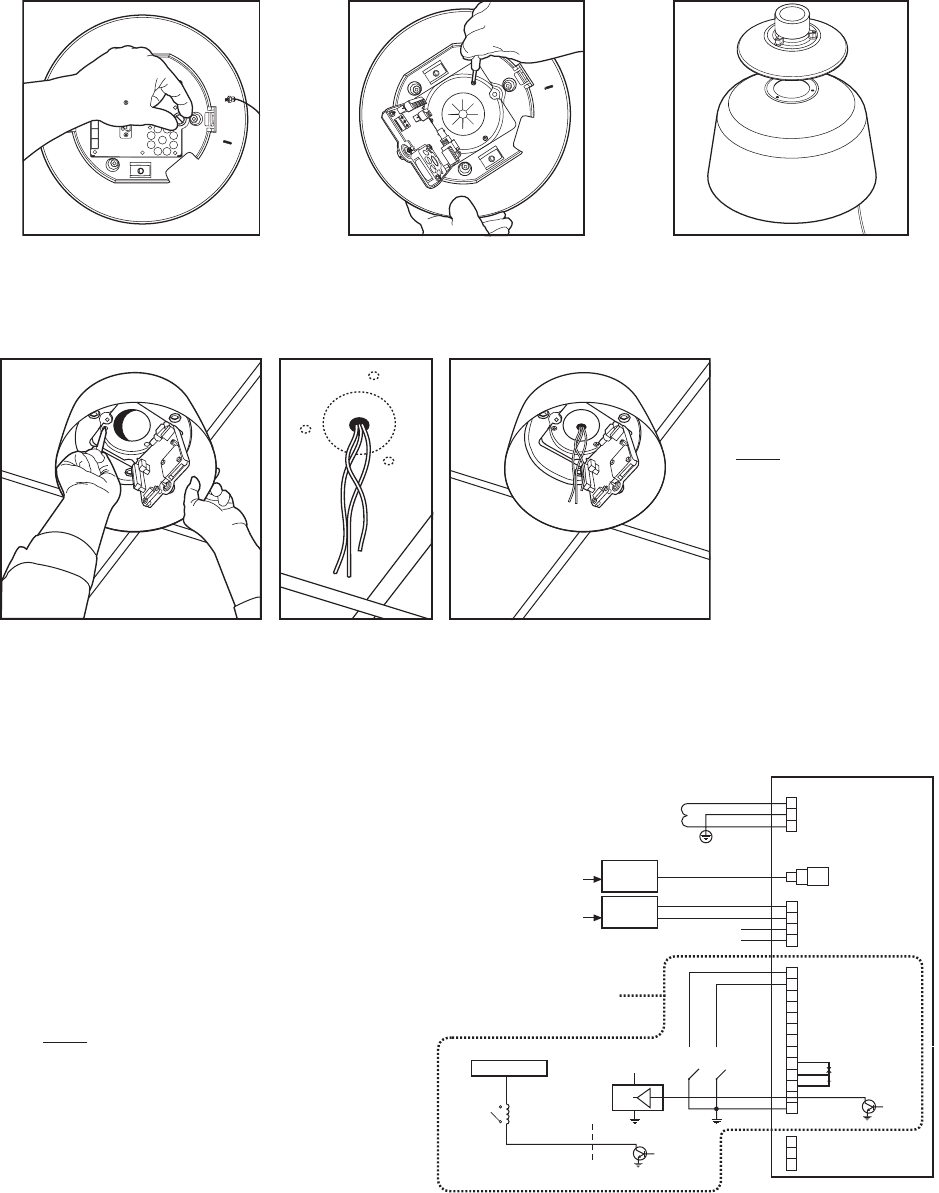
STEP 1 - REMOVE THE TOP PORTION OF THE BACK BOX
a. Turn the thumbscrew and open the
hinged door located inside the back box.
b. Unscrew the three Phillips screws lo-
cated underneath the hinged door.
c. Remove the top portion of the back box.
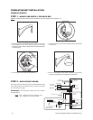
STEP 2 - PREPARE SURFACE AND INSTALL THE BACK BOX
a. Determine the mounting location. Use the base of the back box as a template. Mark the fastener and center hole positions onto the
mounting surface.
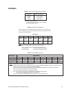
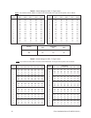
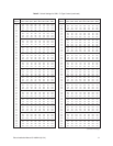
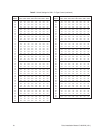
b. Drill a hole in the center of the mounting surface. Pull wiring through the opening. Refer to Tables A and B in the Appendix for wiring
distances. Prepare the holes for the fasteners. Position the back box over the mounting holes and pull wiring into the back box.
Secure the back box to the mounting surface using the appropriate hardware for your installation.
NOTE: If installing outdoors
apply a sealant between the
back box and the mounting
surface
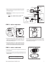
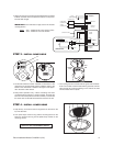
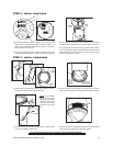
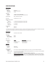
STEP 3 - WIRE CIRCUIT BOARD
Attach the wiring to the interconnect circuit board inside the back
box. Close the door to the back box. Turn on power to the back
box. The red LED will light.
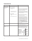
IMPORTANT: If the LED does not light, refer to the
Trouble-
shooting
section.
NOTE: Aux 1 - Maximum 2A at low voltage (<40V)
Aux 2 - Maximum 150 vA at 32 VDC
+5 to +24 VDC
NOT USED
NOT USED
TX-
TX+
VIDEO IN
CONTROLLER
TX-
TX+
RX-
RX+
SWITCHES
(WIRING EXAMPLE)
1
2
3
4
5
6
7
ALARM
INPUTS
GROUND
+5 VDC
AUX 2
HEATER/FAN
(NOT USED)
VIDEO OUT
GROUND
AUX 2
(NO)
(NC)
RELAY
(AUX 1)
CONTROL
(RS-422)
LOGIC GATE
(WIRING EXAMPLE)
EXTERNAL RELAY
(WIRING EXAMPLE)
24 VAC
TRANFORMER
COAXITRON
CONTROLLER
2 WIRE
CONTROLLER
POWER
(24 VAC ONLY)
SPECTRA II ONLY


