


8 Pelco Manual C1431M-C (8/04)
When the power requirements are the same, there are two ways to connect
power:
(1) A three-pin plug is supplied as loose equipment. Connect the wires from
the plug to the camera as follows:
Brown - AC HI
Blue - AC NT
Green - Ground
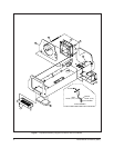
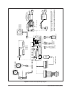
Connect the plug to the CAM 1 socket on the circuit board (remove the
plastic cover over the power supply section of the circuit board).
or
(2) If both the camera and enclosure use 120 VAC and you ordered the op-
tional 120 VAC electrical outlet accessory (O/I-OUTLET), connect the
120 VAC plug to the camera and the three-pin plug to CAM 1 (remove the
plastic cover over the power supply section of the circuit board).
When the power requirements are different, connect the wires from the two-
pin plug, which is supplied as loose equipment, to the camera as follows:
Brown - AC HI
Blue - AC NT
Connect the plug to the CAM 2 socket on the circuit board.
12. Wire power to the enclosure to operate the camera.
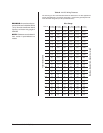
EH5723 and EH5729 Models Only – Wire power directly to the camera.
If you are using 24 VAC, refer to Table A to determine the size of wire to use.
EH5723-1, -2, -3 Models, and EH5729 -1, -2, -3 Models Only –
•
CAM 1 - If the camera’s power input is connected to CAM 1 on the circuit
board, go to step 13.
• CAM 2 - If the camera’s power input is connected to CAM 2 on the circuit
board, wire power for the camera as follows:
a. Connect AC high to connector 9 of the 10-connector INPUTS terminal
block (goes to the brown wire in the CAM 2 connector).
b. Connect AC neutral to connector 10 of the 10-connector INPUTS termi-
nal block (goes to the blue wire in the CAM 2 connector).
13. EH5723-1, -2, -3 Models, and EH5729 -1, -2, -3 Models Only –
Wire power to the enclosure to operate accessories (and the camera if its
power is connected to CAM 1 on the circuit board) as follows:
a. Remove the plastic cover over the power supply section of the circuit
board.
b. Connect AC high to AC HI of the 3-connector terminal block.
c. Connect AC neutral to AC NT of the 3-connector terminal block.
d. Connect ground to GND of the 3-connector terminal block.
e. Reinstall the plastic cover over the power supply section of the circuit
board.
WARNING:
Camera
damage possible.
You
can damage your camera
if you connect it to the
wrong connector.
If your camera will use the same
power as the enclosure, plug the
camera into the CAM 1 socket on
the circuit board.
If your camera’s voltage will be dif-
ferent from the enclosure’s voltage,
plug the camera into the CAM 2
socket.
DO NOT
plug the camera
into the CAM 1 socket or you can
damage your camera. CAM 1 has
enclosure voltage on it.
BE CAREFUL - REMEMBER
CAM 1 IS ENCLOSURE
POWER
NEVER PLUG YOUR CAM-
ERA INTO CAM 1 IF THE
CAMERA’S VOLTAGE IS
DIFFERENT FROM THE
ENCLOSURE’S VOLTAGE.