Pelco Manual C456M-D (1/98) 11
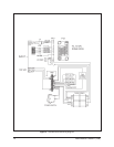
12. If you are not using Coaxitron
®
control, connect the control wiring to RXD+
and RXD-.
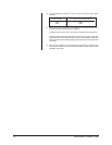
From controller To 4-wire terminal inside back box
TXD+ RXD+
TXD- RXD-
13. Back box installation is now complete. Proceed with the installation of the dome
drive unit. Refer to the manual provided with the dome drive for further instal-
lation instructions.
3.2 PENDANT
1. Install the pendant dome mount. Refer to the instructions supplied with the
mount.
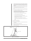
2. The back box is designed to be suspended from a suitable length of 1-1/2"
NPT pipe threaded at both ends. For outdoor model, apply pipe thread sealant
to the pipe before assembly. Install one end of the pipe into the mount. Tighten
to approximately 30 ft/lb and tighten any locking means that may be provided
on the mount.
3. Bring the wiring for the back box through the mount.
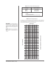
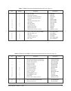
• Video - Refer to Table A for the type of video coaxial cable to use.
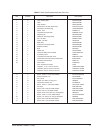
• Power - If the input power to the dome is 24 VAC, refer to Table B to
determine the size of wire to use. For the 120 VAC model, make sure the
wiring can supply power for the heaters and fan as well as the receiver/
driver. Refer to Section 5.0, SPECIFICATIONS, for power requirements.
• Control - If you are using a Coaxitron
®
controller, the control signals to
operate the dome drive will be transmitted over the video coax.
If you are not using a Coaxitron
®
controller, bring wires to the back box
for two RS-485 control lines (RX+ and RX-).
4. Remove the parts bag inside the back box.
5. Outdoor Model Only - Place an O-ring onto the back box mounting pipe.
Push the O-ring up about 4 inches (10 cm) or as far as it will go if the pipe is
not 4 inches long.
6. Outdoor Model Only - Install the pendant cap on the pipe and place the top
side of the cap against the O-ring. Place the second O-ring onto the pipe and
push the O-ring against the bottom side of the pendant cap.
7. Back out the lock screw on the mounting flange of the back box so that the
back box can be screwed onto the mounting pipe.
8. Indoor Model Only - Place the pendant cap on top of the back box.
9. Screw the back box onto the mounting pipe. Tighten the lock screw.
10. Outdoor Model Only - Push the pendant cap down against the top of the
back box. Push the top O-ring against the top of the pendant cap.
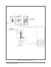
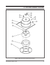
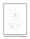
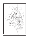
Refer to Figure 3 for the following steps.
11. Install the coaxial cable to the BNC connector.
12. Install power to the 10-position terminal block. Make sure the power switch on
the side of the back box is off.
NOTE:
The length of pipe may cause
noticeable motion on the video dis-
play. If this occurs, additional support
of the pipe by bracing, guy wiring, etc.
will be required.


