


8
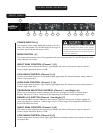
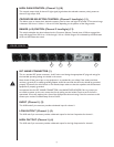
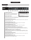
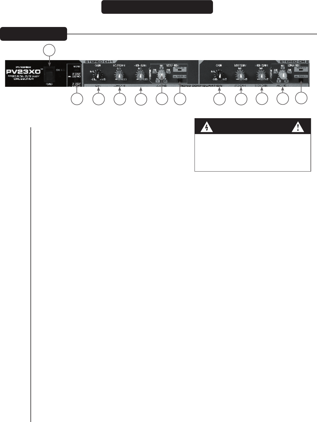
POWER SWITCH (1)
This 2-position rocker switch applies mains power to the unit
when in the ON position. The red LED located to the right of
the Power switch indicates that power is ON.
MODE SWITCH (2)
This switch selects between stereo 2-way operation and mono 3-way operation. The red LED above the Mode
switch indicates mono mode.
INPUT GAIN CONTROL (Channel 1) (3)
This control is used to optimize the channel 1 gain between the mixer and the power amps for channel 1.
Control range is between 0 dB and +12 dB.
LOW GAIN CONTROL (Channel 1) (4)
Controls output level of channel 1 low frequency signal (signal below the selected crossover point) present at
channel 1 low output XLR.
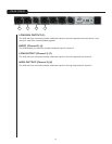
HIGH GAIN CONTROL (Channel 1) (5)
Controls output level of channel 1 high frequency signal (signal above the selected crossover point) present at
channel 1 high output XLR.
CROSSOVER SELECTOR CONTROL (Channel 1 Lows/Highs) (6)
Allows user to choose their desired crossover point for lows and highs for channel 1. Control range is
between 100 Hz and 1 kHz or 1 kHz and 10 kHz depending on the position of the Range Switch.
RANGE (x10) SWITCH (Channel 1 lows/highs) (7)
This switch multiplies the value indicated on the Crossover Selector Control times 10. When engaged, the
range will change from 100 Hz to 1 kHz through 1 kHz to 10 kHz. Range x10 is indicated by illumination of
the red LED above the switch.
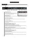
INPUT GAIN CONTROL (Channel 2) (8)
This control is used to optimize the channel 2 gain between the mixer and the power amps for channel 2.
Control range is between 0 dB and +12 dB.
LOW GAIN CONTROL (Channel 2) (9)
Controls output level of channel 2 lows signal (signal below the selected crossover point) present at channel 2
low output XLR.
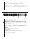
F R ON T PA N E L
S T E R E O M O D E O P E R A T I O N
1
2
4
5
6
7
8
9
12
3
10
11
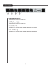
WARNING
THE ON/OFF SWITCH IN THIS APPARATUS
DOES NOT BREAK BOTH SIDES OF THE MAINS.
HAZARDOUS ENERGY MAY BE
PRESENT INSIDE
THE ENCLOSURE WHEN THE POWER SWITCH IS
IN THE OFF POSITION.