


Design and specifi cations are each subject to change without notice. Ask factory for the current technical specifi cations before purchase and/or use.
Should a safety concern arise regarding this product, please be sure to contact us immediately.
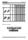
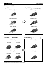
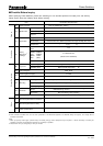
Power Switches
■
Application
Notes
When using our Power Switches, please observe the fol low ing
items (“prohibited items”) and be cautious of the fol low ing
in or der to prevent dangerous ac ci dents and de te ri o ra tion
of per for mance.
1. Prohibited items and notes on mounting
1. Operation position for soldering (including pre heat ing)
Push type switches: Do not solder in the locked con di tion.
Slide type switches: Be sure to switch the lever se cure ly
when soldering.
2. When soldering using a soldering iron, soldering con di tions
vary with the tip shape of the soldering iron, watt age,
and PWB thickness. Thoroughly check the con di tions
in ad vance, including the heat re sis tance rat ing of the
solder.
3. Do not apply a load to terminals when soldering. Care
should be taken in this regard because a load may
deteriorate electric and mechanical characteristics.
4. Since the power switches are not sealed, do not wash
them.
5. When mounting a power switch to a through-hole type
PWB, the infl uence of thermal stress on the switch is
greater than that on one-sided PWB.
Be sure to check the infl uence as well as the heat
re sis tance rating of the solder.
2. Notes on circuit conditions
1.
When a power switch is used with a weak current of less
than 500 mA, the fi lm on the surface of con tact cannot
be bro ken and contact failure may oc cur.
2. The durability of power switches varies with the type
of the switch: those for ac power and those for dc
pow er. When using switches for ac power, check the
durability. When us ing switches for dc power, re view
and check the load conditions of a relevant set.
3. Use the switches within their rating, including in rush
current rating. Check particularly the inrush current
using a switch with a set. Since voltage fl uc tuation
occurs depending on geographical re gion, review the
derating for using a switch.
4.
If load conditions vary in a set to be used, adapt ability
with the switch must be considered. Be sure to check
the above mentioned notes 1 to 3.
3. Prohibited items and notes on mounting and op er at ing
con di tions
1. In principle, operate the center of the lever.
2. For mounting an operation button:
1) Design so that the button is mounted to the cen ter
of the lever.
2) Design so that the load in removal and mount ing of
the button is within the range of the switch’s strength
rating of the operational part.
3. Do not pull the switch rod while it is locked. Oth er wise,
the self-lock ing func tion may be broken, re sult ing in a
lock ing fail ure or mal func tion. Make sure that the switch
is re leased es pe cial ly when attaching/de tach ing a but ton
to the rod and as sem bling/dis as sem bling the target
prod uct. (This ap plies to the self-lock ing switches) Set
the strength for de tach ing your but ton (knob) from our
switch rod to a max i mum of 10 N in order to minimize
the pos si bil i ty of a break down of the locking func tion.
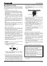
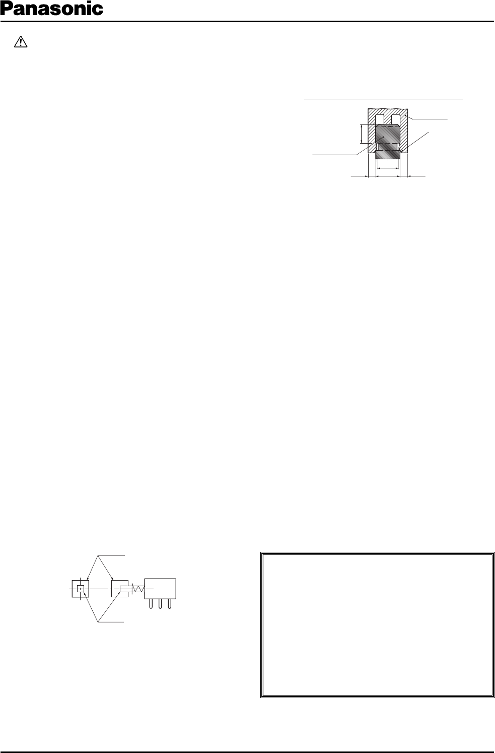
When de sign ing your but ton, re fer to the following
shape and dimensions.
Before adopting our switches, check the requirements
carefully.
4. When mounting a switch to a set, check the switch
ON/OFF setting and the position of the op er a tion al part
(slide type, rotary type, etc.).
5. Design and use so that external stress is not
continuously applied to the soldering parts (solder lugs
and PWB terminals) with a switch mounted in a set.
6. In actual operating conditions, do not use switch es
un der ambient temperatures above 70 °C.
7. Avoid the following ambient surroundings and oth er
con di tions because they may affect per for mance:
●
Under an atmosphere of corrosive gas such as Cl
2
,
H
2
S, NOx, or SO
2
●
In atmospheres of residual water drops, dew
con den sa tion, or adhesive water drops
●
In liquids such as water, salt solution, oil, chem i cals,
and organic solvents
●
In direct sunlight
●
In dusty locations
4. Prohibited items and notes on storage con di tions
Since contact characteristics and soldering quality may
de te ri o rate due to sulfuration and oxidation of con tacts
and ter mi nals, pay heed to the following items.
1. For storage and transport of the switches, avoid
unpacking them, and store them at room tem per a ture
and room humidity. Use them as soon as pos si ble,
gen er al ly with in 3 months, or within a max i mum of 6
months after de liv ery.
2. Do not store the switches under conditions of high
tem per a ture and/or high humidity, or in a location
where cor ro sive gas may be generated.
3. If some units remain after unpacking, store them af ter
applying adequate moisture-proof and gas-proof
treat ment.
5. For use in equipment for which safety re quest ed
Although care is taken to ensure switch quality,
vari a tion of contact resistance (increase), short
cir cuits, open cir cuits, and temperature rise are
some prob lems that might be generated.
To de sign a set which places maximum emphasis
on safety, review the affect of any single fault of
a switch in advance and perform virtually fail-safe
design to ensure maximum safety by:
1. preparing a protective circuit or a protective
de vice to improve system safety, and
2. preparing a redundant circuit to improve sys tem
safety so that the single fault of a switch does
not cause a dangerous situation.
6. For actual use, be sure to refer to “Product Spec i fi ca tions
for Information.”
Reference of Customer's button design
Button
Lever
(2.5)
(3.0)
(3.3)
(0.6)
Switch rod top
Customer's
button
(0.6)
(R1.2)
Mar. 2005