21
8 Disassembly and Assembly Instructions
8.1. Outdoor Unit
8.1.1. CU-E9GFE-2 CU-E12GFE-2
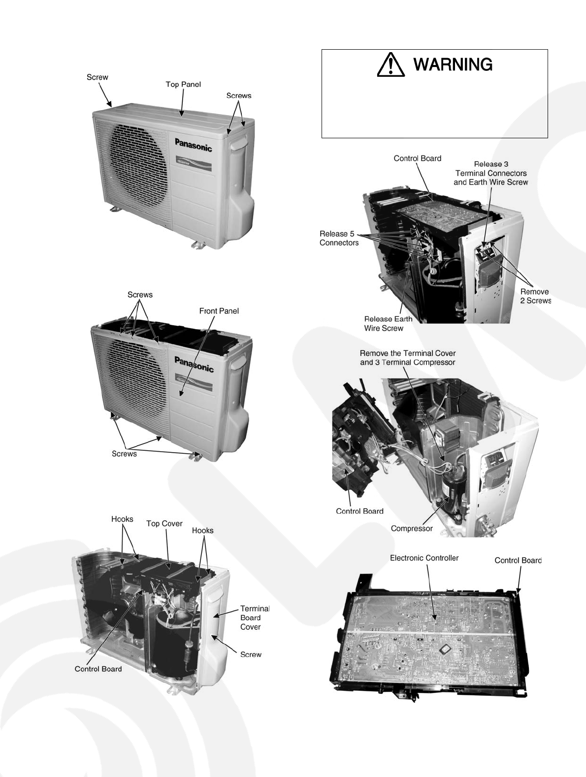
1. Remove the 3 screws of the Top Panel.
Fig. 13
2. Remove the 6 screws of the Front Panel.
Fig. 14
3. Remove the screw of the Terminal Board Cover.
4. Remove the Top Cover of the Control Board by 4 hooks.
Fig. 15
5. Remove the Control Board as follows:
Fig. 16
Fig. 17
Fig. 18
• Be save to return the wiring to its original position
• There are many high voltage components within the heat
sink cover so never touch the interior during operation.
Wait at least two minutes after power has been turned
off.


