


12
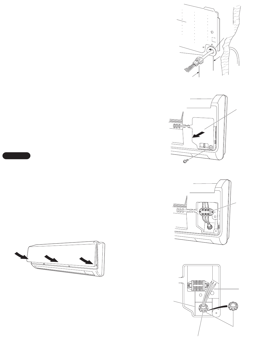
3-7. Wiring Instructions for Inter-unit Connections
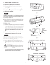
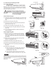
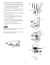
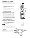
(1) Insert the inter-unit wiring (according to local codes)
into the through-the-wall PVC pipe. Run the wiring
toward the indoor side allowing approx. 10" (25 cm)
to extend from the wall face. (Fig. 24)
(2) Grasp both ends of the air intake grille, and remove
it by opening towards the front and pulling towards
you.
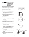
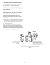
(3) Remove the screw on the right side cover plate and
open the cover. (Fig. 25)
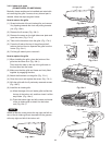
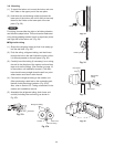
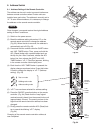
(4) Route the inter-unit wiring from the back of the
indoor unit and pull it toward the front for connec-
tion. (Figs. 26a and 26b)
(5) Connect the inter-unit wiring to the corresponding
terminals on the terminal plate (Figs. 26a and 26b)
while referring to the wiring diagram.
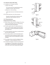
(6) Be sure to secure the wiring with the provided
clamp.
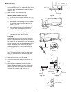
When closing the air intake grille, press the bottom right
and left corners and center. (Fig. 27)
Please refer to “How to replace the grille” on page 9 or
10 for installing the air intake grille.
NOTE
Rear
panel
Wiring
Wall
10"
(25 cm)
Plastic
cover
Fig. 24
Cover
Fig. 25
Terminal
plate
Fig. 26a
Inter-unit
wiring
/RFNQXW
Earth
plate
Top of conduit
connector
Fig. 26b
Fig. 27