


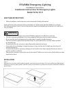
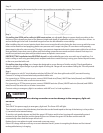
Step 2:
Remove cover plate by first removing the screw caps and then unscrewing the screws. Save screws.
Step 3:
If installing into OPEN wall or ceiling in NEW construction, set adjustable flange to proper depth according to the
thickness of the drywall you plan to use. Measure height and depth of installation and use two of the four screws - to
anchor the flange to the stud. A standard hanger bar can also be utilized for more stability.
After installing the unit, secure interior plastic dust cover to metal unit box by lining the dust cover up with the screw
holes on the metal box and applying gentle even pressure until it snaps into place. If cover does not fit properly,
please tape in place for extra securing. This dust cover protects important electronic components within the unit from
dust and debris, leave dust cover in place until final wiring connections are made and then discard. Final step is to
install front painted cover plate with provided screws and plastic screw covers.
If RETROFITTING installation into EXISITING drywall, set adjustable flanges to be even with top of metal box. Cut
hole in ceiling or wall using provided plastic template and secure metal housing in using your desired drywall screws,
or the ones provided with unit.
If installing into drop ceiling, use a hanger bar designed to secure fixtures of similar weight. (Check specification
sheet for weight.) Adjust flanges to proper depth of ceiling tile. Flange will secure above ceiling tile. This will provide
additional support.
Step 4:
With no power to unit (AC circuit breaker switched off) feed AC wire through knockout (KO) on metal housing.
Connect AC wiring to internal wire leads provided within unit.
For connecting to 120Vac power source, connect BLACK lead wire (Phase), WHITE lead wire (Neutral) and GREEN lead
wire (Ground). Use wire nuts on all wire connections.
For connecting to 277Vac power source, connect ORANGE lead wire (Phase), WHITE lead wire (Neutral) and GREEN
wire (Ground) Use wire nuts on all wire connections.
Connect wiring to emergency light in accordance with NEC and / or local regulations.
Be sure to not cross the wires during connection or serious damage to the emergency light unit
can occur.
Step 5:
Turn ON AC the power supply to emergency light unit. The Green LED will light.
Then securely connect the white battery lead wire that can be found taped to the top of the battery, to the positive
(+) terminal on the internal battery.
To test the unit, gently depress and hold the green LED button and the lens housing will automatically extend
outward to the open position and the lamps will turn on. Release the green LED button and the unit will
automatically retract and the lamps will turn off.
Replace front cover plate via metal screws and screw cap covers.
Green LED charge indicator will stay on as an indication that AC power is energizing the fixture and the internal
rechargeable battery is charging.
CAUTION