


ENGLISH
4
Operating Instructions
To Operate
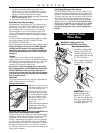
Make sure disposable paper filter dust bag is in place. DO NOT
operate the cleaner without a paper filter dust bag. Plug the
power cord into an electrical outlet and press the
ON (l) - OFF
(O) switch on Helping Handle Assembly, or on top of base for
Straight Handle Models when ready to operate.
General Information
The performance of your new cleaner greatly depends upon care
and maintenance. The instructions in this manual will guide you in
performing basic care and maintenance. To obtain the most
satisfying years of service read the instructions and keep them
handy for future reference.
Operating Recommendations
This new ORECK XL High-Speed Upright is one of the finest,
fastest, and strongest units in its class. You’ll love the way it
cleans, gets under things, and it’s SO lightweight and easy to
use.
The following ar
e a few simple suggestions r
egar
ding its
operation:
1. When inserting a new disposable paper filter dust bag—
FIRST PUFF OUT and OPEN THE BAG.
2. When the disposable filter dust bag is full, REPLACE IT.
3. If at any time the machine does not pick up properly or
makes an unusual noise, STOP OPERA
TION and service.
4. Although your upright will pick up pins, paper clips, and
other small objects, it is recommended that these be
r
emoved fr
om the floor befor
e you vacuum. Failur
e to do so
may r
esult in per
manent damage to the motor suction fan
and its housing.
5.
WARNING: Do not use your vacuum cleaner on damp or
wet surfaces. This will cause damage to the vacuum cleaner
and is dangerous to the user. Damage caused by use on wet
or damp surfaces is not covered under warranty.
6. REPLACE THE BELT EVERY 6 MONTHS.
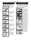
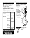
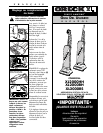
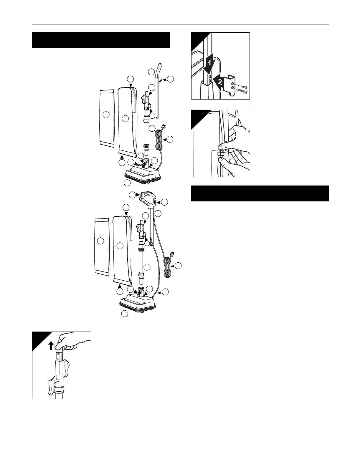
Assembly
1
2
3
4
9
10
11
14
15
12
13
5
6
7
8
1
2
3
4
5
9
6
8
7
10
11
14
12
13
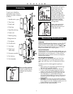
T
o assist you in identifying
components of your vacuum,
the parts have been numbered
as follows
:
1 Handle section, upper
2 Tube, lower
3 Power head
4 Outer bag
5 Paper filter dust bag
6 Power cord
7 Retaining spring
8 Bag tension bar
9 Zip fastener
10 On/off switch
11 Cord hook
12 Plastic loop/
cable clamp
13 Connector assembly
14 Fan housing
15 Cord assembly
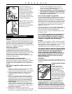
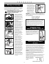
1
Before assembling appliance,
remove two screws from the
connector assembly. Remove
car
dboar
d inser
t by pulling
upward.
With ON/OFF switch facing
the front of the unit, slide
upper handle section over
matching section of the
connector assembly. Place
brace against handle and
connection assembly aligning
the holes. Insert short screw
into top hole and long screw
into the bottom hole then
tighten firmly until handle is
no longer loose.
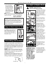
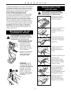
2
3
Upper
Handle
Connector
Assembly
Attach cord to cord clip by
pressing cord above and
below clip ensuring the cord
is fully rested in clip.