


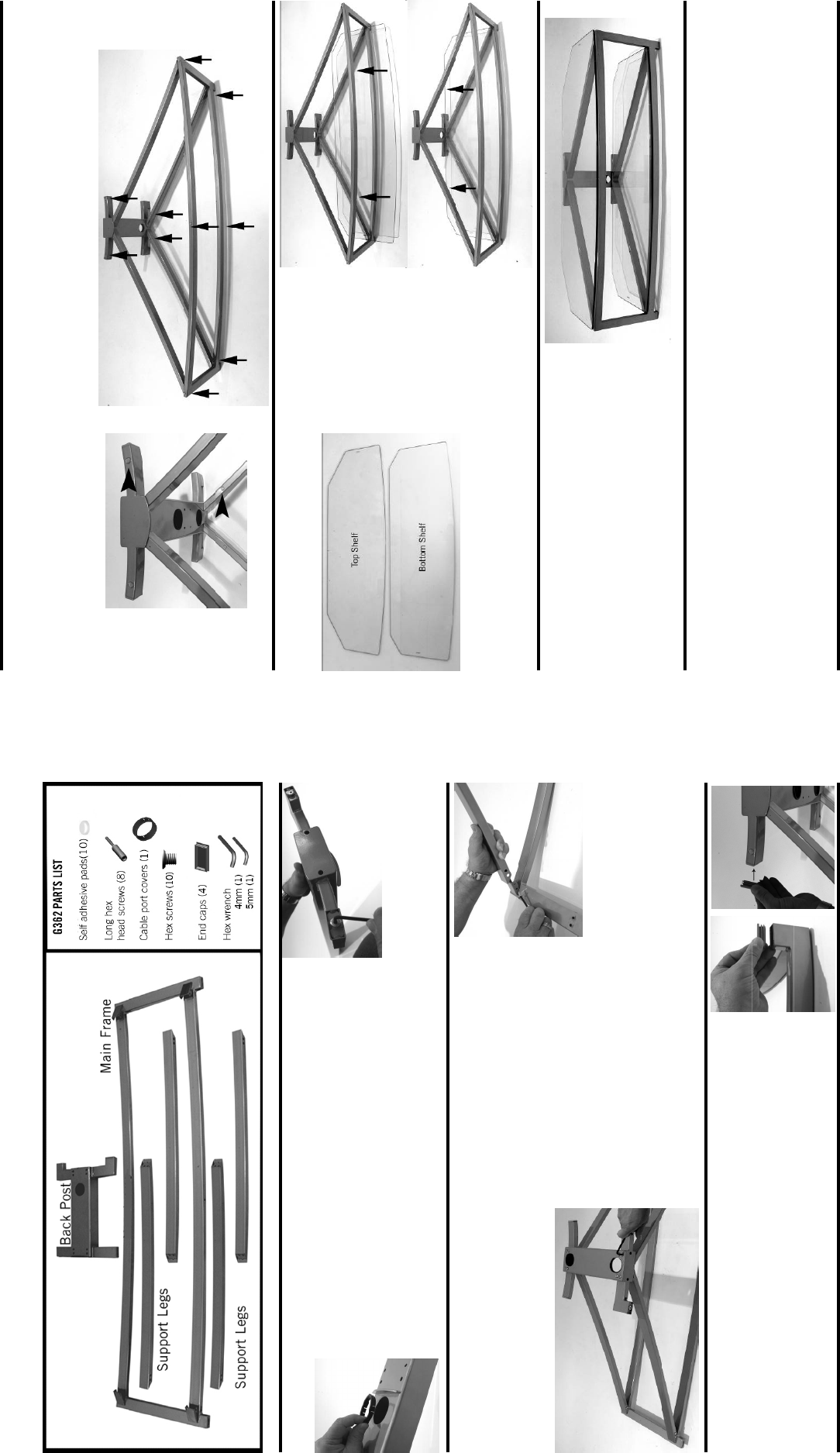
Step 1
Install hex screw into pads on bottom of back post. (Fig. 1a)
Install cable port covers into back post. (Fig. 1b)
Fig. 1a
Fig. 1b
Step 2
Lay main frame face down on floor.
Match holes on support legs to holes on main frame support brackets.
Loosely secure support legs to main frame using hex head screws and supplied hex
wrench. (Fig. 2a)
Secure back post to support using long hex head bolts and supplied hex
wrench. (Fig. 2b) Tighten all support leg screws.
Stand table upright.
Fig. 2a
Step 3
Install end caps into foot sections on front of base frame and side of back
frame. (Figs. 3a & 3b)
Fig. 3a
Fig. 3b
Model: G362
Fig. 2b
Step 4
Place adhesive rubber pads on support legs and main frame. (Figs. 4a & 4b)
Rock the stand to check that it is level and stable.
Note: For unstable condition, un-screw shortest leveling foot until table sits level.
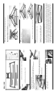
Step 5
Identify glass shelves. (Fig. 5a)
Slide bottom shelf onto lower frame members. (Fig. 5b & 5c)
Fig. 4b
Fig. 4a
Fig. 5a
Fig. 5b
Fig. 5c
Step 6
Place top shelf onto upper frame members. (Fig. 6)
Caution: Never try to move table by pulling on glass
shelves. Always move table by grasping the frame.
Fig. 6
Specifications are subject to change without prior notice.
Every effort has been made to provide accurate and error-free assembly and installation. OmniMount Systems disclaims
liability for any difficulties arising from the interpretation of information contained in these instructions. If OmniMount
products are used for purposes other than their original intent, OmniMount, its distributors and retailers shall not be
held responsible or liable for injuries or property damage, direct, indirect, or consequential, which may arise from the
inability to use this product safely, properly, and in the manner for which it has been designed and manufactured. War-
ranty does not apply to products which have been lost, damaged by misuse, abuse, or accident.