


PX791 & PX792 SERIES
OMEGA® SANITARY PRESSURE TRANSDUCER
INSTRUCTION SHEET
Mounting
Although the unit can withstand normal vibra-
tion without damage or significant output
effects, it is always good practice to mount the
transducer where there is minimum vibration. Be
sure to use a gasket that does not interfere with
the sanitary diaphragm. If the gasket I.D. is
smaller than 1.50 inches, an offset due to
clamping force will occur.
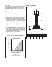
Power Supply
The supply voltage for the 1-5 and
1-6 Vdc output transducers must be within the
range of 10 to 36 Vdc. The maximum supply
voltage for a 4-20mA current output transducer
is 36 Vdc while the minimum supply voltage is
dependent upon the loop resistance of the circuit.
Refer to Figure 1. The loop supply voltage vs.
loop resistance shows the minimum supply
voltage (V
min
) required for a given loop resistance
(R
LOOP
).
WARNING!
This instrument is susceptible to damage when exposed to static
electrical charges. To avoid damage to the transducer observe the
following:
• Ground the body of the transducer BEFORE making any electrical
connections
• When disconnecting, remove the ground LAST.
NOTE: The braided shield and drain wire in the cable (if supplied) is not
connected to the transducer body, and is not a suitable ground.
CAUTION: Pressure spikes in excess of the rated overpressure capabil-
ity of the transducer may cause irreversible electrical and/or mechani-
cal damage to the pressure measuring and containing element(s).
Excitation (Ratiometric Output Only)
For proper operation a voltage within the range
of 5 to 10 Vdc must be applied between the
transducer’s supply terminals.
Noise
For minimum noise susceptibility, avoid running
the transducer’s cable in a conduit that contains
high current AC power cables. Where possible
avoid running the cable near inductive equipment.
Shield Wiring
Connect the braided shield to the guard terminal
on the reading instrument (meter, etc.) if avail-
able or to ground or to the power supply nega-
tive terminal.
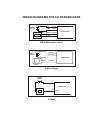
Adjustment Potentiometers
The zero and span pots are accessible through
the top of the case. Loosen the four screws and
separate the top carefully. The zero pot is marked
with a white dot.