


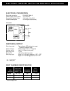
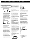

a) Adjusting the switching point.
Case 1 or Case 2
Press and hold the SP button. The display
will show the previous switching pressure
setting, and the dotted bar will flash while
the button is pressed down (case 1).
You can now use the cursor keys to adjust
the switching point upwards or downwards.
If a cursor key is held down, the values will
change faster. When the cursor key is
released again, the switch-on pressure
setting will cease to change. This setting is
stored and activated when the SP button is
released, after which the display will show
the current pressure value and the bar will
quit flashing.
b) Adjusting the reset point.
Case 3 or Case 4
Press and hold the RP button. The display
will show the previous reset pressure
setting, and the dotted bar will flash while
the button is pressed down.
You can now use the cursor keys to adjust
the reset point in the same manner as
described above.
During both adjustment operations, it may
occur that the hysteresis graph changes
from one state to another at the time a
transition is made through the point
"Switching pressure = Reset pressure".
When both points are correctly set, the
hysteresis graph will also be correct. You
can change between SP and RP as often as
you wish until the settings are correct.
c) Setting a buffering time.
In order to prevent brief pressure “spikes”
or “surges” from causing undesired
switching, a buffering time can be entered.
The effect of this is that pressure changes
are evaluated only if the pressure signal in
question is present for longer than the
buffering time. In order to set a buffering
time, press the button SP before the power
supply is switched on. Release this button
again after the power supply has been
switched on. The display will then show the
buffering time in milliseconds (e.g. 03) or
seconds. The cursor buttons ▼, ▲ can be
used to set the buffering time to 03, 06,
12, 24 or 50 ms or 0.1, 0.2 or 0.4
seconds. When this has been done, press
SP to store the setting.
d) Setting the pressure switch to ambient
pressure = 0.
Since ambient pressure varies according to
altitude, the user may re-calibrate the zero
point to match local conditions.
Press the button RP before the power
supply is switched on. Release this button
again after the power supply has been
switched on and the display test has run.
The display will then show "OFS". The
cursor buttons ▼, ▲ can be used to set the
pressure display to 0. When this has been
done, press SP to store the setting.
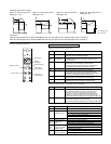
e) Hysteresis mode
If it is desired to operate with a fixed
hysteresis value instead of the reset point,
this value can be selected as desired.
In order to set a hysteresis value, the two
buttons SP and ▼ must be pressed
simultaneously before the power supply
is switched on.
Release these buttons again after the
power supply has been switched on and the
display test has run. The display will then
show the operating mode. The cursor
buttons ▲,▼ can now be used to change
the operating mode until "HYS" appears in
the display. When this has been done,
press SP to store the setting.
The SP button can be used to display the
switching-point setting, which can be
modified by means of the cursor buttons
▲,▼.
The button RP can be used to display the
hysteresis setting, which can also be
modified by means of the cursor buttons
▲,▼.
Negative hysteresis means: Signal “on”
with rising pressure (case 1).
Positive hysteresis means: Signal “on” with
falling pressure (case 2).
If the switching point is modified, this will
automatically also result in a change in the
reset point by a value equal to the
hysteresis setting.
Case 1
Case 2
f) Window mode
If it is desired to monitor whether the pressure
lies within a certain range, a switching window
can be created for this purpose. The pressure
switch will then indicate cases in which the
actual pressure lies above or below this area.
In order to set a switching window, the two
buttons SP and ▼ must be pressed
simultaneously before the power supply is
switched on.
Release these buttons again after the power
supply has been switched on and the display
test has run. The display will then show the
operating mode.
The cursor buttons ▲,▼ can now be used to
change the operating mode until "FEn"
(standing for "Window") in the display. When
this has been done, press SP to store the
setting. The button SP can be used to display
the switching-point setting, which can be
modified by means of the cursor buttons ▼, ▲.
The distance between the switching point and
reset point is the switching window. If the
switching point is lower than the reset point, a
signal will be output as long as the pressure
lies within the preset window (case 1, rising
pressure). If the switching point is higher than
the reset point, a signal will be output as long
as the pressure lies outside the preset window
(case 2, rising pressure). In the case of falling
pressure, the signal is inverted.
Case 1
Case 2
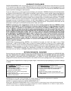
Std = Standard mode, switching and reset
points adjustable
HYS = Hysteresis mode, switching point and
hysteresis adjustable
FEn = Window mode, switching window
adjustable
QQ
pp
QQ
pp
INSTRUCTION MANUAL
Off = Pressure within window
1
0
RP < SP
p
On = Pressure within window
SP < RP
p
1
0
Positive hysteresis
1
0
Switching point
p
Negative hysteresis
1
0
Switching point
p
ADJUSTING THE SWITCHING POINTS (SP)
AND RESET POINTS (RP)