


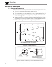

2
2
- ** means:
-MA : 4 to 20 mA current output
-V1 : 0 to 5 Vdc output
-V2 : 0 to 10 Vdc output
-K : K type thermocouple output
-MVC : 10 mV/ºC output
-MVF : 10 mV/ºF output
The following table lists the optional accessories:
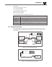
2.2 – Electrical Connection
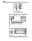
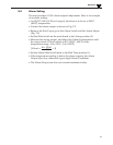
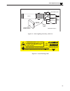
The shielded cable provides the power and output connections. Fig 2-1 shows
the wiring diagram for different analog outputs. Fig. 2-2 shows alarm output
connections.
Figure 2-1. General Wiring Diagram
Figure 2-2. Alarm Output Wiring Diagram
Accessories
Model No. Description
OS137-MB Mounting Bracket
OS137-WC Water/Air Cooling Jacket with Built-in Air Purge Collar
OS137-AP Air Purge Collar
OS137-LS Laser Sighting
PSR-24S Regulated 24 VDC (400 mA) Power Supply
CAL-3-IR NIST Traceable Calibration
Installation
RED
WHITE
12-24 Vdc
POWER SUPPLY
-OR-
10 mV/Deg
0/5 Vdc or 4-20 mA
or 0/10 Vdc
EARTH
GROUND
DIGITAL
VOLTMETER/
AMMETER/
RECORDER
BLACK
SHIELD
+
+
–
–
YELLOW
THERMOCOUPLE
METER/
RECORDER
RED
K TYPE
THERMOCOUPLES
+
–
OS137
WHITE
12-24 Vdc
POWER SUPPLY
EARTH
GROUND
BLACK
SHIELD
+
–
OS137
+
–
MECHANICAL
RELAY
BLACK
GREEN