


START HERE
2
34
Thermocouple Wire Connection
1. Connect positive (+) lead of thermocouple.
2. Connect negative (-) lead of thermocouple.
Note: The negative lead is red.
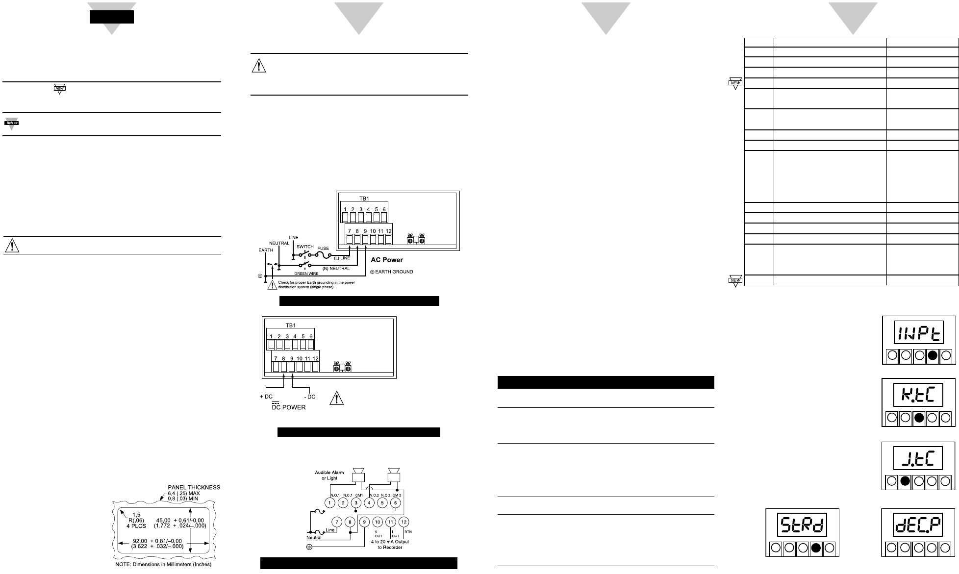
Example hook up for AC Load
Alarm 1 (Setpoint) Hook-up
1. Connect a jumper from ac Line to Relay 1 Common
(Terminal 3).
2. Connect Relay 1 Normally Open (Terminal 1) to External
Alarm ac Line.
3. Connect External Alarm to ac Neutral.
Alarm 2 (Setpoint) Hook up
1. Connect a jumper from ac Line to Relay 2 Common
(Terminal 6).
2. Connect Relay 2 Normally Open (Terminal 4) to External
Alarm ac Line.
3. Connect External Alarm to ac Neutral.
Analog Output Wiring for 4 - 20 mA Current
1. Connect Positive Lead to Terminal 11.
2. Connect Negative Lead to Terminal 12.
For 0 -10 Voltage
1. Connect Positive Lead to Terminal 10.
2. Connect Negative Lead to Terminal 12.
Using This Quick Start Manual
Use this Quick Start Manual with your controller to make
changes to the thermocouple type, decimal point, units, and to
change the setpoints.
Features with are for the “B” version which has three-
color programmable “Big” LED display - All segment
characters shown are for the “B” version.
For detailed instructions, refer to the appropriate section
in the Operator’s Manual.
Before You Begin
In addition to the meter and the related parts, you will need
the following items to set up your meter:
• ac power, as listed on meter’s ID/Power Label
• Thermocouple
• 1/8” flat blade screwdriver
Mount the Unit
1. Cut a panel opening using
the dimensions shown to
the right.
2. Position the unit in the
opening, making sure the
front bezel is flush with the
panel.
3. Install retaining clip on the
meter and tighten against
the panel.
Wiring
1. Remove the panel at the back of the unit.
2. Locate the TB1 connector.
3. Insert the correct wire in each terminal as shown in the
following figure and tighten the lockdown screws.
4. Tug gently on the wires to verify the connections.
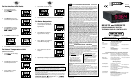
AC Powered Unit Connections
External Fuse Required:
Time-delay, UL 248-14 listed Time-lag, IEC 127-3 recognized
175 mA (115 Vac line) 125 mA (115 Vac line)
80 mA (230 Vac line) 63 mA (230 Vac line)
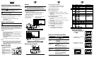
In order to maintain the same degree of
protection as the AC units, always use a
Safety Agency Approval DC source with
the same Overvoltage Category and
Pollution Degree.
-+
TB4B
TB4C
-+
TB4B
TB4C
Warning: Do not connect AC power to your device until you
have completed all input and output connections. This
device must only be installed by a specially trained
electrician with corresponding qualifications. Failure to
follow all instructions and warnings may result in injury!
Safety Consideration
This device is marked with the international Caution symbol.
The instrument is a panel mount device protected in
accordance with EN61010-1 (Safety requirements for electrical
equipment for measurement, control, and laboratory standard).
Remember that the unit has no power-on switch. Building
installation should include a switch or circuit-breaker that must
be compliant to IEC 947-1 and 947-3.
SAFETY:
• Do not exceed voltage rating on the label located on the
top of the instrument housing.
• Always disconnect power before changing signal and
power connections.
• Do not use this instrument on a work bench without its
case for safety reasons.
• Do not operate this instrument in flammable or explosive
atmospheres.
• Do not expose this instrument to rain or moisture.
EMC:
• Whenever EMC is an issue, always use shielded cables.
• Never run signal and power wires in the same conduit.
• Use signal wire connections with twisted-pair cables.
•
Install Ferrite Bead(s) on signal wire close to the instrument
if EMC problems persist.
Wiring the Controller
Typical Wiring of TB1
Using the Configuration Menu
To configure the meter, you use the buttons on the front panel.
To: Take This Action:
Display the Press the MENU button. The first function
Configuration Menu on the menu, INPT, displays.
Select a submenu 1. Press MENU until the function you
function want is shown.
2. Press ᮣ/DEV.
The information you can change flashes.
Select a value 1. Press ᮡ/MAX to display the option
for that submenu you want.
function 2. Press MENU to store it.
STRD quickly flashes, indicating that
the selection has been stored in memory.
Then the next menu function displays.
Go back to previous Press RESET once.
menu function
Exit the Press RESET twice. The unit displays
Configuration RST as it reinitializes. When a numeric
Menu value displays, the unit is in run mode.
(Optionally, you can press MENU to
move through all the menu functions
until the unit reinitializes.)
MENU SUBMENU ᮣ/DEV DESCRIPTION
INPT J.TC, K.TC
*
, DJ.TC, T.TC Input
DEC.P FFFF
*
, FFF.F Decimal Point
RD.CF R.1=C, R.1=F
*
Reading Configuration
COLR GRN, RED, AMBR Display Color
S1.CF S.1=A
*
, S.1=B
Setpoint 1 Configuration
S.2=U
*
, S.2=L
S2.CF S.1=A
*
, S.1=B
Setpoint 2 Configuration
S.2=U
*
, S.2=L
S1.DB 0003
*
Setpoint 1, Deadband
S2.DB 0003
*
Setpoint 2, Deadband
OT.CF O.1=E
*
, 0.1=D Analog Output
O.2=C
*
, 0.2=V
Configuration
O.3=A
*
, 0.3=P
O.4=D, 0.4=R
O.5=F, 0.5=H
P.BND 0000 shown if 0.3 = P Proportional Band
M.RST 0000 shown if 0.3 = P Manual Reset
OT.S.O RD!1, OUT1, RD!2 , OUT2
Output Scale & Offset
CJ.OF 0000
Cold Junction Offset
LK.CF RS=E
*
, RS=D
Lockout Configuration
SP=E
*
, SP=D
L3=0
*
, L3=1
BRIT M.BrT, L.BrT, H.BrT
Display Brightness
* Factory Default Settings.
DC Powered Unit Connections
Using the Menus
To Change the Thermocouple Type:
1. Press MENU until the display
shows INPT
2. Press
ᮣ
/DEV to show current
thermocouple type:
3. Press
ᮡ
/MAX to select the
setting from J, K, T or DJ.TC.
4. Press MENU to store the value.
5. Press RESET twice to display the current temperature.
ᮡ
ᮣ
SETPTS /DEV MENU RESET
/MAX
ᮡ
ᮣ
SETPTS /DEV MENU RESET
/MAX
ᮡ
ᮣ
SETPTS /DEV MENU RESET
/MAX
ᮡ
ᮣ
SETPTS /DEV MENU RESET
/MAX
ᮡ
ᮣ
SETPTS /DEV MENU RESET
/MAX