


Copyright 2008 Omega Engineering, Inc. M - 4644 / 0408 FR# R7-443649-00
PARAMETERS
SP
r0
r1
r2
d0
c0
c1
Lc
Hc
P1
P5
H5
Description
Set Point
Differential or Hysteresis
Low Value Set Point
Higher Value Set Point
Heating or Cooling Control
Min. stop time for Load
Continuous Cycle Time
HR Value for 4 mA Input
HR Value for 20 mA Input
Probe Adjustment (shifting)
Probe Type
Parameter Access code
Units
%
%
%
%
Option
Minutes
Hours
%
%
%
Range
Numeric
Range
r1 to r2
1 to 99
0 to r2
r1 to 100
Hu/dH
0 to 59 min.
0 to 24 hrs
0 to 100
50 to 100
0 to 10
0-1 V, 0-3 V, 4-20 mA
0 to 99
(SET AT 0 FROM FACTORY)
PARAMETERS DESCRIPTION
SP = Set Point - Desired Regulation Temperature
r0 = Differential or Hysteresis
r1 = Lower Set Point Limit
r2 = Higher Set Point Limit
d0 = Humidifying / Dehumidifying Control -
Humidifying
: To choose Humidifying Control: Set d0 = Hu.
The output is activated when the relative humidity is less than
the Set Point (SP) - r0 and disconnected if the relative
humidity is > = SP.
Dehumidifying
: To choose Dehumidifying Control: Set
d0 = dH. The output is activated when the relative humidity
is > SP + r0 and disconnected when the relative humidity is
< = SP.
c0 = Minimum Times Between Start and Stop.
c1 = Continuous Cycle Time. The time the load is connected when
a continuous cycle is activated. To view the programmed
cycle time for display, press the down arrow button for 8
seconds. The display with blink as indicated. The output will
be connected during the number of hours indicated by the
c) parameter. To cancel the Continuous cycle, press and hold
the down arrow button again for 8 seconds.
Lc = RH value for 4 mA input. Parameters for use with 4 to 20 mA
output probe.
Hc = RH value for 20 mA input. Parameters for use with 4 to 20
mA output probe.
P1 = Probe Adjustment. Offset degrees to adjust probe. If the probe
is not placed in the exact point that is to be measured, use a
standard hygrometer and adjust the difference with this
parameter.
P5 = Probe Type. (Set from the factory.) DO NOT ADJUST.
H5 = Access to Probe Parameters. (The code is set to 0 from
the factory.)
PARAMETER PROGRAMMING
Set Point (SP) is the only parameter the user can access with-
out code protection.
• Press SET. SP text will appear on the display.
• Press SET again. The real value is shown on the display.
• The value can be modified with the UP and DOWN arrows.
• Press SET to enter any new values.
• Press SET and DOWN at the same time to quit programming
or wait one minute and the display with automatically exit
programming mode.
* The keyboard code can be reset to ZERO by turning off the con-
troller and turning it on again while keeping the SET key depressed.
Access to all code protected parameters.
• Press SET for 8 seconds. The access code value 00 is shown
on the display. (Unit comes with code set at 00 from factory).
• With the UP and DOWN arrows, code can be set to user needs.
• Press SET to enter the code. If code is correct, the first
parameter label is shown on the display (SP).
• Move to the desired parameter with the UP and DOWN keys.
• Press SET to view the value on the display.
• The value can be modified with the UP and DOWN arrows.
• Press SET to enter the value and exit to text parameter.
• Repeat until all necessary parameters are modified.
• Press SET and DOWN at the same time to quit programming
or wait one minute and the display will automatically exit
programming mode.
LED INDICATIONS
OUT This indicates the load is connected. The system waits for
the programmed minimum stop time of the load.
DISPLAY MESSAGES
In normal operation, the humidity will be shown on the display. In
case of alarm or error, the following messages will be shown:
ER = Memory Error
-- = Short-Circuit Probe Error
oo = Open Probe Error
In the event an error occurs, the unit follows a fixed working cycle
which connects the load for 5 minutes and then disconnects the
load for 5 minutes alternately.
MAINTENANCE / REPAIR
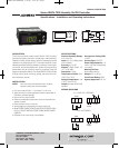
Upon final installation of the Series RHCN-7000 Digital Humidity
Switch, no routine maintenance is required. A periodic check of
system calibration is recommended. The devices are not field
repairable and should be returned to the factory if recalibration or
other services is required. After fir obtaining a Returned Goods
Authorization (RGA) number, end the material, freight prepaid, to
the following address. Please include a clear description of the
problem plus any application information available.
Omega Engineering
Attn: Repair Department
One Omega Drive
Stamford, CT 06907
OMEGA ENGINEERING, INC.
One Omega Drive
PO Box 4047
Stamford, CT 06907
PH: 1 - 203 - 359 - 1660
H-RHCN-7000:TEMPLATE 6/18/08 8:10 AM Page 2