


2
FIGURE 2
FIGURE 3
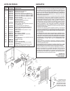
GROUNDING CLIP DETAIL
FIGURE 4
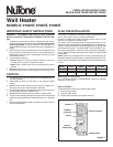
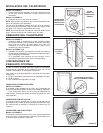
INSTALL THE HEATER
Refer to FIGURE 2
1. Remove heater assembly from housing. Take out the four (4)
screws shown and set heater assembly aside.
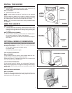
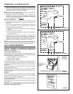
Refer to FIGURE 3
2. Attach housing to wall studs.
NOTE: Locate housing at least 12" from floor on any adjacent
walls.
Use the measuring guides on the sides of housing to position
housing so that it will be flush with finished wall. Nail the housing
to studs through the hole and slot on both sides of housing.
NOTE: In 24"-on-center stud construction, framing in between studs
is necessary.
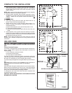
WIRE THE HEATER
Refer to FIGURE 4
1. Connect power cable to housing. Attach electrical power cable
to housing using appropriate connector. Allow 6" of wire inside
housing. Secure ground wire to housing with grounding clip,
as shown.
Refer to FIGURE 5 and FIGURE 6
2. Wire the heater assembly. Connect wires from heater assem-
bly to power cable wires. Follow wiring diagram.
If heater is wired direct, use the built-in thermostat for tempera-
ture control.
OPTIONAL WIRING CONVERSIONS
When using a separate wall control, simply turn the heater's built-
in thermostat to its highest setting. There is no need to disconnect
the built-in thermostat:
a) Turn built-in thermostat to highest setting.
b) Remove knob.
c) Fasten security cover to grille.
LINE-VOLTAGE THERMOSTAT
Refer to FIGURE 7
If wall-mounted control is desired, use the Model 86W Line-Volt-
age Thermostat. Purchase thermostat separately.
Cut blue wire. Strip ½” of insulation from each end. Connect wires
from wall control to each stripped wire.
LOW-VOLTAGE THERMOSTAT
If wall-mounted control is desired, use a Model 82 Transfomer/
Relay with an appropriate low-voltage thermostat (purchase sepa-
rately). Follow the mounting and wiring instructions packed with
the controls.
HALF-WATTAGE CONVERSION
Refer to FIGURE 8
The heater will produce less heat and use less electricity if con-
verted to half-wattage. Remove the black jumper wire from the
heating element and discard wire.
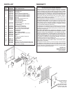
HEATER
ASSEMBLY
MOUNTING
SCREWS
THERMAL
OVERLOAD
“RESET”
BUTTON
THERMOSTAT
MEASURING
GUIDES
NAIL HERE –
BOTH SIDES
FIGURE 5