


29
JUMPER
OPTIONAL PUMP TIMER
1 LOAD
2 LINE
3 NEUT.
4
5
RWC
YG
24VAC THERMOSTAT CONNECTIONS
GND
TRANSFORMER
24V
NC
NO
NO C
C
NC
120V
LINE
NEUTRAL
NO
NC
com
HIGH
Speed Select
red
white
blue or brown
black
yellow
Door Interlock
Switch
3
0
2
0
FAN MOTOR
FAN
CAPACITOR
PUMP
black
yellow
blue
MED-HIGH
MED
CAF-01
0101
2
1
Continuous/Automatic
Ventilation Switch
WARNING
1 AMP
MAX
FUSE
* NOTE: Units with
an (Optional) Pump
Timer do not get an
(Optional) Temperature
Sensor
* OPTIONAL
TEMPERATURE
SENSOR
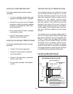
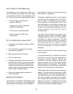
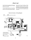
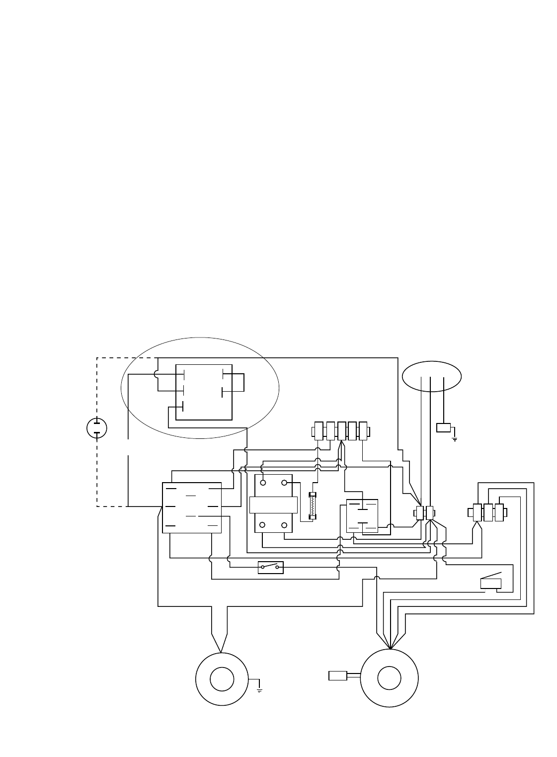
The Clean Air Furnace operates at 120V, singles
phase and draws anywhere from 2-8.7 amps,
depending on fan speed.
The low voltage thermostat (not provided)
connects to the R & W terminals for heating and
the R & Y & C terminals when calling for cooling.
Caution should be used if installing a setback
thermostat to control the system. If the
thermostat is set back too far, and, for example,
is set to call for a lot of heat when you get out of
bed, at which time showering and general water
use is at its peak, then the hot water heater may
not keep up.
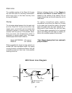
Clean Air Furnace - Wiring Diagram
To change fan speed, move
bottom wires on the speed
select terminal block to the high,
med-hi or med location.
Note:
Unit is shipped on high speed.
R - W = Heat
R - G = Fan Only (optional dehumidistat)
G - R - Y - C = A/C
Electrical