


10-30
Page 3
2008-02-15
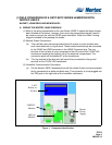
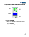
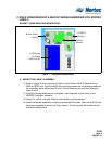
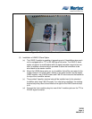
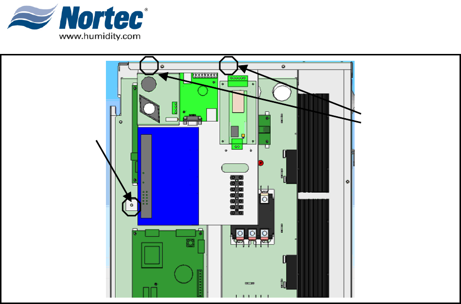
Figure 2. LINKS 2 Bracket Placement
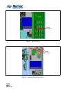
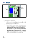
B. WIRING THE NORTEC LINKS 2 MODULE
(1) Most of the wiring connections for the Nortec LINKS 2 module will have already
been finished at the factory, however, there are a few connections that will need to
be made to connect the module to the NHDI/SC series humidifier. Refer the LINKS
2 wiring diagram included in the package for details.
(2) Module Wire Connections:
(a) There will be a wire harness provided that will consist of a red and blue wire,
each terminated with a bare end. These wires should already be connected
to the 24VAC and GND terminals on the LINKS 2 terminal strip. Both wires
will be connected to the 5-pole connector labelled X1 (Main Supply) located
on the humidifier support board. The red wire is to be connected to the
terminal labelled L1. The blue wire is to be connected to the terminal labelled
N.
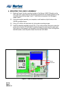
(b) A loose ribbon cable with a 10-pin header plug and a 20-pin header plug will
be included with the kit. The 20-pin header plug should be connected to the
J2 connector on the TTL-to-RS485 converter located on the back of the
LINKS 2 mounting bracket. The 10-pin header plug should be connected to
the COM PORT connector located on the NHDI/SC Logic Board.
Use 8-32
screws
with nuts
Use 8-32
screw
only.