


STEAM LINE AND CONDENSATE RETURN LINE
1. Refer to the installation manual of the steam
distribution system used in your application.
Steam Distributor Form #XX-231, SAM-e
Form #XX-249, and Blower Pack Form
#XX-277.
ELECTRICAL
PRIMARY VOLTAGE SUPPLY WIRING TO
HUMIDIFIER
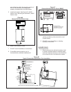
1. Check and ensure that available voltage and
phase corresponds with operating voltage and
phase of humidifier as indicated on the
humidifier spec label, see Figure #1.
2. Ensure that an adequate power supply is
available to carry full humidifier amperage
drawn as specified by rated amps on the
humidifier spec label, reference to local codes.
3. A dedicated external disconnect must be
installed. Do not exceed the maximum circuit
protection amps as indicated on the
nameplate label.
4. Connect ground wire to cabinet ground clamp.
Do not use neutral wire of four wire supply as
ground.
5. Single phase humidifiers may be run on three
phase power, but load may unbalance power
grid.
6. External wiring sizes must be in accordance
with NEC and/or CEC and existing local
electrical codes and by-laws.
PRIMARY VOLTAGE SUPPLY WIRING FROM
HUMIDIFIER(S) TO BLOWER PACKS
1. All blower packs are wired (by others) to be
powered from the humidifier.
2. As a safety feature, blower packs come
equipped with a manual reset safety
thermostat and relay built into the blower pack
cabinet. The manual reset thermostat turns
off the humidifier if the blower pack gets
overheated. The control thermostat, mounted
on the steam distributor, starts the fan when
steam is generated.
3. All blower packs have high efficiency blowers
to minimize the frontal and overhead
clearance required to absorb the steam.
-7-
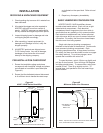
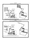
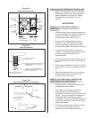
Clampand1.5”IDHose
FactorySupplied
Installa2”O.DCopperPipefortheNHSC
modeland2”O.D.StainlessSteelPipefor
theNHDImodel(byothers).
InstallaCopperFunnelfortheNHSCmode
l
andaStainlessSteelFunnelfortheNHDI
model(byothers).
A
ir
Gap
NOTE: Steam hose should not
reach bottom of the funnel.
Figure #12
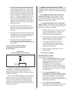
Drain Connection
7.95
(20.2)
Drain
Connection
1.5" O.D.
Supply Water
Connection
3/8“
Drain
Water Cooler
Connection 3/8”
Optional
Cooling Ki
t
for SSR
(consult
factory)
Power
Inlet
Controls
Inlet
NHSC
Scale
Collector
Tank
23.0
(58.4)
A
B
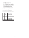
Model
010-090
135-180 Left
135-180 Right
A (in.)
1.7”
1.7”
1.7”
B (in.)
5.4”
5.4”
20.3”
Figure #11
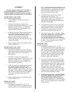
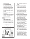
Drain Line Connection
Humidifier
Drain Line
Floor
Surface
Line
Recommended Model
Gould - Model SSH
Consult Factory
Figure #13
Drain Pump by others (if necessary)