


temperature are uniform and representative of
spaces being humidified.
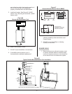
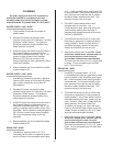
3. Mount duct high limit humidistat
downstream of steam distributors far enough
that, under normal humidity and air flow
conditions, steam will have been fully
absorbed (typically at least 10 feet). It must
be located to sense high humidity only when
uniform and representative air is
over-humidified or approaching saturation.
4. Mount duct air-proving switch so that it is
able to sense air flow or lack of it. Wire it to
make when air flow is sensed and break when
air flow fails.
5. Check operation of all on/off controls before
starting humidifier.
6. Calibration of controls (on/off or modulation) in
the field may be necessary due to shipping
and handling. Verify humidistat accuracy
before commissioning system.
OPTIONAL MODULATION (CONTINUOUS
CONTROLS)
1. Read on/off controls section first since it is
necessary to all control systems.
2. Virtually any modulation (continuous control)
external hardware by others (as long as it has
%RH set-point circuitry) may be interfaced
with pre-specified factory-configured pc board
via the control terminal strip.
3. Modulation (continuous control) by others for
use with NHSC / NHDI humidifiers involves
one of several control wiring diagrams. In all
cases, modulating signal interfaces through
control terminal strip to main pc board inside
humidifier.
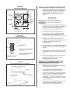
4. For set-point control at the humidifier an
integrated controller can accept a direct
transducer signal. The accuracy of the
humidifier to changing conditions will be
dependant on the accuracy of the signal.
5. The modulation signal must increase from
minimum toward maximum as sensed RH
(actual RH) drops below desired RH (%RH
set-point). In response, humidifier’s steam
output will increase from minimum toward
maximum. When humidifier’s steam output
(lbs/hr) matches humidification load (lbs/hr),
modulation signal will stabilize.
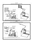
6. Field-wiring connections for modulation control
are to be made to external side of terminals
28, 30 and 32 on humidifier’s control terminal
strip. Always refer to the external control’s
wiring diagram factory supplied with each
NORTEC modulation control option.
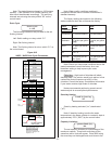
7. Varying dc Voltage Modulation Signal
Powered by Others: NHSC / NHDI
humidifiers can be factory configured to accept
the following vdc signals: 0-10 vdc, 0-20 vdc,
1-5 vdc or 2-10 vdc. Wire according to
NORTEC supplied external wiring diagram
that comes with each modulation option. To
share the signal with more than one
humidifier, wire in parallel to each humidifier.
If a different signal is desired consult factory.
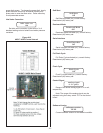
8. Varying dc milliAmp (mA) Modulation
Signal Powered by Others: NHSC / NHDI
humidifiers can be factory-configured to
accept a standard dc mA signal, if
pre-specified. Wire according to NORTEC
supplied external wiring diagram that comes
with each modulation option. Choose from
0-20 dc mA or 4-20 dc mA. To share the
signal with more than one humidifier consult
factory.
9.
Varying Resistance (W) Modulation by
Others: NHSC / NHDI humidifiers can be
factory configured to power a 3-wire varying
resistance modulation humidistat by others, if
pre-specified. Wire according to NORTEC
supplied external wiring diagram that comes
with each modulation option. Choose from
0-500W or up to 0-1000W. To share the signal
with more than one humidifier consult factory.
-10-
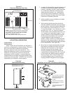
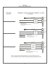
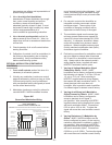
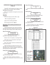
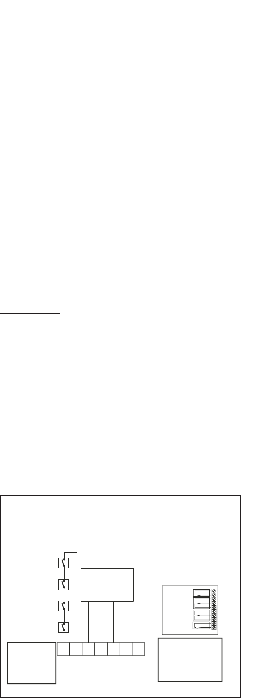
NHSC / NHDI SERIES
CONTROL CIRCUIT TERMINAL BLOCK
IMPORTANT: READTHESEINSTRUCTIONSCAREFULLY BEFORECONNECTING CONTROL WIRING
NOTE: If no On/Off
Control is used, then
Afield jumper must
be connected across
8 and 10 in order for
humidifier to operate
NOTE: See Included Diagram(s) For Accessory Wiring Instructions
8
32 30 28
61
Control
Humidistat
Air Proving
Switch
High Limit
Humidistat
Other On/Off
Devices
Optional
Modulation Control
See Diagram included
with unit for details
10
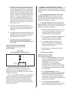
Optional external remote
indication.Any or all of these
remote indications can be
utilized. Refer to Trouble
Shooting Manual for system
status indication.
NHDI: Dry Points, rated 24 Vac/dc 1.0Amp
s
max. resistive load per Indicator
OPTIONAL REMOTE
STATUS PCB
K1 Steam
K4 Unit ON
K3 Service
K2 Error
Figure #16
Generalized Modulation Wiring