


Typical Application Information
TLF12040–17
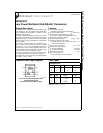
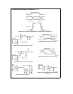
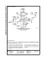
FIGURE 17 Typical RS-485 Bus Interface
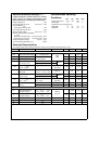
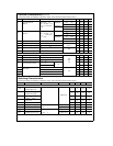
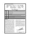
TABLE I Device Pin Descriptions
Pin No Name Description
1 RO Receiver Output When RE (Receiver Enable) is LOW the receiver is enabled (ON) if DORI
t
DORI by
200 mV RO will be HIGH If DORI
s
DORI by 200 mV RO will be LOW Additionally RO will be HIGH for
OPEN (Non-terminated) Inputs
2REReceiver Output Enable When RE is LOW the receiver output is enabled When RE is HIGH the receiver
output is in TRI-STATE (OFF)
3 DE Driver Output Enable When DE is HIGH the driver outputs are enabled When DE is LOW the driver outputs
are in TRI-STATE (OFF)
4 DI Driver Input When DE (Driver Enable) is HIGH the driver is enabled if DI is LOW then DORI will be LOW
and DORI will be HIGH If DI is HIGH then DORI is HIGH and DORI is LOW
5 GND Ground Connection
6 DORI Driver OutputReceiver Input 485 Bus Pin
7DORI Driver OutputReceiver Input 485 Bus Pin
8V
CC
Positive Power Supply Connection Recommended operating range for V
CC
is
a
475V to
a
525V
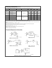
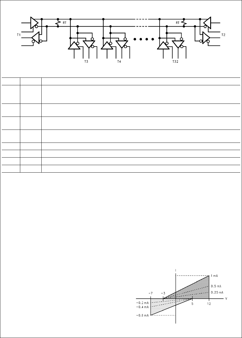
Unit Load
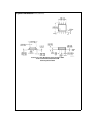
A unit load for an RS-485 receiver is defined by the input
current versus the input voltage curve The gray shaded re-
gion is the defined operating range from
b
7V to
a
12V The
top border extending from
b
3Vat0mAto
a
12V at
a
1mA
is defined as one unit load Likewise the bottom border
extending from
a
5Vat0mAto
b
7V at
b
08 mA is also
defined as one unit load (see
Figure 18
) An RS-485 driver
is capable of driving up to 32 unit loads This allows up to 32
nodes on a single bus Although sufficient for many applica-
tions it is sometimes desirable to have even more nodes
For example an aircraft that has 32 rows with 4 seats per
row would benefit from having 128 nodes on one bus This
would allow signals to be transferred to and from each indi-
vidual seat to 1 main station Usually there is one or two less
seats in the last row of the aircraft near the restrooms and
food storage area This frees the node for the main station
The DS36C278 the DS36C279 and the DS36C280 all have
unit load and unit load (UL) options available These
devices will allow up to 64 nodes or 128 nodes guaranteed
over temperature depending upon which option is selected
The UL option is available in industrial temperature and
the UL is available in commercial temperature
First for a UL device the top and bottom borders shown
in
Figure 18
are scaled Both 0 mA reference points at
a
5V
and
b
3V stay the same The other reference points are
a
12V at
a
05 mA for the top border and
b
7V at
b
04 mA
for the bottom border (see
Figure 18
) Second for a UL
device the top and bottom borders shown in
Figure 18
are
scaled also Again both 0 mA reference points at
a
5V and
b
3V stay the same The other reference points are
a
12V
at
a
025 mA for the top border and
b
7V at
b
02 mA for
the bottom border (see
Figure 18
)
The advantage of the UL and UL devices is the in-
creased number of nodes on one bus In a single master
multi-slave type of application where the number of slaves
exceeds 32 the DS36C278279280 may save in the cost
of extra devices like repeaters extra media like cable
andor extra components like resistors
The DS36C279 and DS36C280 have an additional feature
which offers more advantages The DS36C279 has an auto-
matic sleep mode function for power conscious applica-
tions The DS36C280 has a slew rate control for EMI con-
scious applications Refer to the sleep mode and slew rate
control portion of the application information section in the
corresponding datasheet for more information on these fea-
tures
TLF12040–19
FIGURE 18 Input Current vs Input Voltage
Operating Range
httpwwwnationalcom7