


9
W415-0527/ 09.29.05
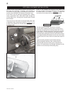
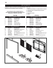
1. Remove the hearth pads and the blower access cover.
(FIGURE 9)
2. Install the blower using the optional blower installation
instructions.
3. Pull the black and white thermal disc wires through the
7/8” bushing in the blower access cover.
4. Cut the white wire as close to the connector as
possible. (FIGURE 11).
5. Cut the red wire as close to the plug as possible.
(FIGURE 11)
6. Using a box connector, connect supply wire through
the junction cover plate located on the right sidce of
the fi rebox enclosure.
7. Connect the red and white wires to the power supply.
Attach the ground to the ground screw on the junction
plate cover.
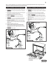
8. Replace the blower access cover.
9. Attach the black & white wires to the back of the
thermal switch and install at the rear of the fi rebox
using the thermal switch support bracket as circled in
(FIGURE 9).
10. Replace the hearth pads.
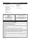
WITH THERMAL SWITCH BRACKET
THERMAL DISC
WHITE
RED
BLACK
BLOWER
VARIABLE
SPEED
SWITCH
FIGURE 11
1. Remove the hearth pads and blower access cover.
(FIGURE 9)
2. Install the blower using the optional blower installation
instructions.
3. Cut the red wire as close to the plug as possible.
4. Cut the black wire as close to the fl ag connection as
possible. (FIGURE 12).
5. Using a box connector, connect supply wire though
the junction cover plate located on the right side of the
fi rebox enclosure.
6. Attach the ground to the ground screw on the junction
plate cover.
7. Replace the blower access cover plate and hearth
pads.
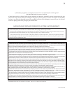
WITHOUT THERMAL SWITCH BRACKET
THERMAL DISC
WHITE
RED
BLACK
BLOWER
VARIABLE
SPEED
SWITCH
FIGURE 12
G
R
O
U
N
D
S
C
R
E
W
1
2
3
4
5
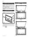
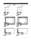
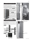
1. Hearth Pads
2. Blower Access Cover
3. Thermal Switch Support Bracket
4. 7/8” Bushing
5. Junction Box
FIGURE 9
Note: In either application it is necessary to remove the variable speed switch from the wiring harness and
install into an electrical switch box as per electrical codes.