


5
W415-0153 / A / 10.29.01
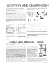
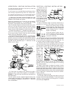
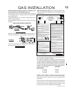
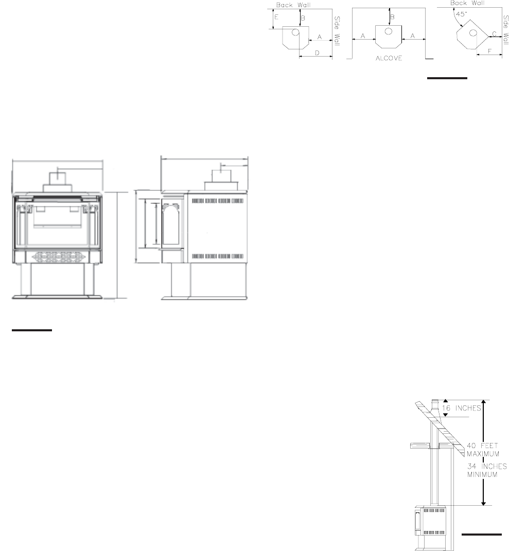
MAINTAIN THESE MINIMUM CLEARANCES TO
COMBUSTIBLES:
A. 7" D. 14
3
/
4
"
B. 2" E. 4"
C. 1"
* F. 9½"
NO ADDITIONAL FLOOR PROTECTION IS REQUIRED
MINIMUM
20" FROM STOVE TOP TO CEILING
*AT A DISTANCE OF 1" FROM THE WALL, ACCESS TO THE BLOWER
SWITCH
, ON-OFF SWITCH OR THE BLOWER POWER CORD MAY
NOT
BE PRACTICAL.
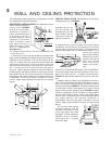
A terminal shall not terminate directly above a sidewalk
or paved driveway which is located between two sin-
gle family dwellings and serves both dwellings. Local
codes or regulations may require different clearances.
Do not allow the inside liner to bunch up on horizontal or
vertical runs and elbows. Keep it pulled tight. A 1-1/4" air
gap all around between the inner liner and outer stove pipe
is required for safe operation.
Use a firestop when penetrating interior walls, floor or ceil-
ing.
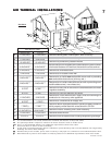
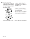
LOCATION AND CLEARANCES
Provide adequate ventilation and combustion air.
Provide adequate accessibility clearance for servicing
and operating the stove.
Never obstruct the front opening of the stove.
GDS28 AND GS28:
As long as clearance to combustibles is kept within the
required distances, the most desirable and beneficial lo-
cation for a Napoleon stove is in the centre of a building,
thereby allowing the most efficient use of the heat created.
The location of windows, doors and the traffic flow in the
room where the stove is to be located should be consid-
ered. If possible, you should choose a location where the
vent will pass through the house without cutting a floor or
roof joist.
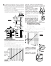
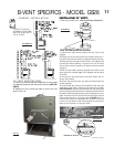
FIGURE 2
VENTING LENGTHS AND AIR TERMI-
NAL LOCATIONS
Use only Wolf Steel or Simpson Dura-Vent Model DV-GS
venting components. Minimum and maximum vent lengths,
for both horizontal and vertical installations, and air termi-
nal locations for either system are set out in this manual
and must be adhered to. For Simpson Dura-Vent, follow
the installation procedure provided with the venting com-
ponents. Both Wolf Steel and Simpson Dura-Vent venting
components may have a 0" rise per foot on horizontal runs.
When using Wolf Steel venting components, use only the
following vent kits: WALL TERMINAL KIT GD175 (7-1/2' of
venting included), or 1/12 TO 7/12 PITCH ROOF TERMINAL
KIT GD110, 8/12 TO 12/12 ROOF TERMINAL KIT GD111,
FLAT ROOF TERMINAL KIT GD112 or STOVE PERISCOPE
KIT GD180 (for wall penetration below grade) in conjunc-
tion with the appropriate venting components.
For optimum performance, it is recommended that all
horizontal runs have a minimum ¼ inch rise per foot.
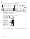
DIRECT VENT SPECIFICS - GDS28
These vent kits allow for either
horizontal or vertical venting of
the stove. FIGURES 3, 4, & 5.
The maximum number of 4"
flexible connections is two hori-
zontally or three vertically (ex-
cluding the stove and the air
terminal connections).
When terminating vertically, the
minimum vertical rise is
34 inches above the stove and
the maximum vertical rise is
40 feet.
Deviation from the minimum vertical vent length can
create difficulty in burner start-up and/or carboning.
Use an adjustable pipe as the final length of rigid pip-
ing to the stove for ease of installation.
FIGURE 1
15"
WINDOW OPENING
11¼"
22½"
26
3
/
4
"
7"ø AIR
INTAKE
FIGURE 3
17
3
/
4
"
12"
10"
4"ø
FLUE
18½"
5½"
GAS LINE ACCESS HOLE
LOCATED IN PEDESTAL
BASE