


17
W415-0496 / B / 08.10.05
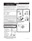
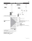
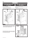
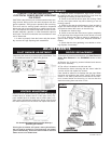
1. Attach the adjustable pipe to the last
section of rigid piping. Secure with screws
and seal.
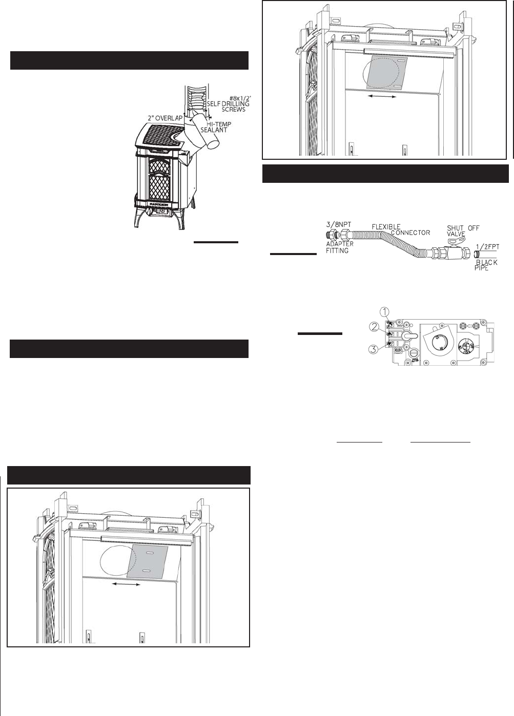
2. Install the 4" aluminium flex-
ible liner to the stove. Secure
with 3 screws and flat wash-
ers. Seal the joint and screw
holes using high tempera-
ture sealant.
3. Run a bead of high tem-
perature sealant Mill Pac
around the inside of the air
intake collar. Pull the adjust-
able pipe a minimum 2" into
the air intake collar.
ENSURE THAT THE SEALANT IS NOT VISIBLE ON THE
EXTERIOR PIPES ONCE INSTALLATION IS COM-
PLETED. AN OPTIONAL DECORATIVE BRASS BAND
IS AVAILABLE FOR THIS USE. (STANDARD WITH A
GD175 KIT AND GD-176). IN THE EVENT THAT THE
VENTING MUST BE DISASSEMBLED, CARE MUST BE
TAKEN TO RESEAL THE VENTING.
In Canada, mobile home installation may be vented hori-
zontally or vertically. In the United States, it may only be
installed vertically. See "Vertical Venting" or "Horizontal Air
Terminal Installation" for installation.
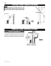
For mobile home installations, the fireplace must be fas-
tened in place. It is recommended that the fireplace be
secured in all installations. Use the levelling/securing kit,
GDSLL-KT for this purpose.
FIGURE 26
STOVE VENT CONNECTION
MOBILE HOME INSTALLATION
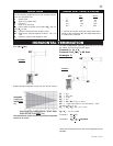
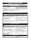
1. Install rigid black pipe, or 1/2" type L copper tubing with
a shut-off valve to the stove.
2. Seal and tighten the gas line securely to a flex connector.
DO NOT KINK FLEXIBLE CONNECTOR.
3. Check for gas leaks by brushing on a soap and water
solution. DO NOT USE OPEN FLAME.
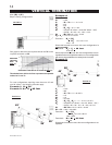
For ease of accessibility, an optional remote wall switch
or millivolt thermostat may be installed in a convenient
location. Route 2 strand solid core millivolt wire from
the gas stove to the wall switch / millivolt thermostat.
The recommended maximum lead length depends on
the wire size: WIRE SIZE MAX. LENGTH
14gauge 100 feet
16gauge 60 feet
18gauge 40 feet
Disconnect the existing wires from terminals 1 and 3 (from
the on/off switch) and replace with the leads from the wall
switch/millivolt thermostat.
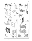
FIGURE 28
FIGURE 29
GAS INSTALLATION
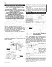
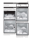
7. In the attic, slide the vent pipe collar down to cover up
the open end of the shield and tighten. This will prevent
any materials, such as insulation, from filling up the 2" air
space around the pipe.
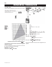
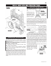
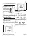
RESTRICTOR
SHOWN IN A FULLY
CLOSED POSITION
RESTRICTING VERTICAL VENTS
Vertical installations may display a very active flame.
Loosen the two screws and slide the restrictor plate
blocking the exhaust path. This reduces the velocity of the
exhaust gases, slowing down the flame pattern and creat-
ing a more traditional flame appearance. For vertical vents
greater than 15 feet, this restrictor must be fully closed.
FIGURE 27
RESTRICTOR
SHOWN IN A FULLY
OPEN POSITION