


5
W415-0360 / 11.05.02
STOVE INSTALLATION
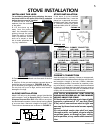
If the stove is to be installed
on a combustible floor, it must be
placed on a approved non-com-
bustible hearth pad, that extends
8" (200mm) beyond the stove
sides and back, and 18" (455mm)
to the front.
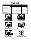
SINGLE WALL CHIMNEY CONNECTOR*
DOUBLE WALL CHIMNEY CONNECTOR
CHIMNEY CONNECTION
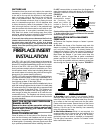
Vent the stove into a masonry chimney or an approved,
insulated solid-fuel stainless-steel chimney with as short
and straight a length of six-inch (150mm) diameter
smoke pipe as possible. Connection to a masonry chim-
ney must be by a metal or masonry thimble cemented
in place. An insulated stainless steel chimney must be
supported at the ceiling or roof and its installation must
comply with its manufacturer's instructions.
THE TOTAL HORIZONTAL VENT LENGTH
SHOULD NOT EXCEED 40% OF THE CHIMNEY
HEIGHT ABOVE THE STOVE.
All horizontal smoke pipe must slope slightly
upwards a minimum of 1/4" per foot (6mm/
0.3m) and all connections must be tight and
secured by three sheet metal screws equally
spaced.
An uninsulated smoke pipe shall not pass
through an attic, roof space, closet or similar
concealed space, or through a floor, ceiling,
wall or partition, or any combustible construc-
tion.
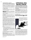
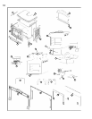
INSTALLING THE LEGS
To avoid being damaged during shipping, the stove
has been bolted to the pallet and must be unbolted
before the stove can be installed.
1. Remove the 4 nuts and
washers from the underside
of the pallet.
2. Lift the stove up and
away from the pallet to
clear the threaded studs
sticking through the pallet.
Place the stove on its back
onto a protective surface
such as a carpet or blan-
ket to avoid scratches dur-
ing leg installation.
3. Remove the four additional nuts from each of the four
studs.
4. Use four of the nuts and washers removed above to
install the legs as illustrated in FIGURES 2a & 2b.
5. Lift the stove up and gently set down on all four legs.
Do not pivot unit up on its legs, as this could result in
damage to the legs.
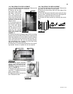
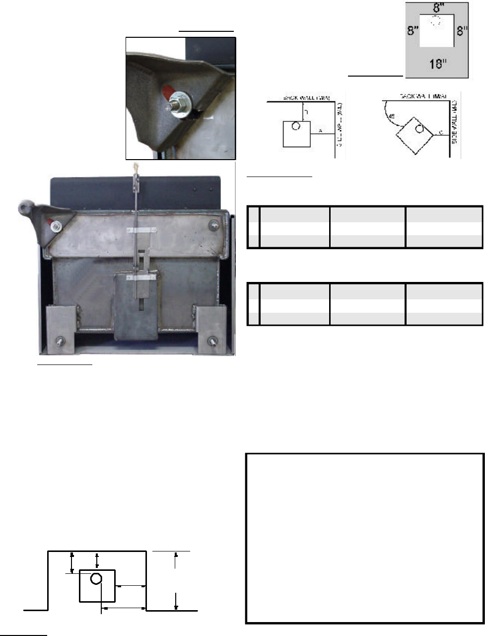
ALCOVE INSTALLATION
Model 1100 only may be installed, using a listed double
wall connector, such as Security DL6 in Canada, the
Simpson Duravent Plus DVL in the USA or an equiva-
lent double wall connector, into an alcove having a depth
of no more than 4 feet and a height of at least 7 feet.
The minimum clearances are as shown in FIGURE 3.
STOVE INSTALLATION
FIGURE 2B
FIGURE 2A
FIGURE 3
9"
6"
14"
23"
ALCOVE
4 FOOT
MAX.
FIGURE 4B
FIGURE 4A
1100/1100L 1400/1400L 1900
A 12" (305mm) 12" (305mm) 22" (560mm)
B 10" (254mm) 12" (305mm) 12" (305mm)
C 6" (152mm) 6" (152mm) 8" (205mm)
1100/1100L 1400/1400L 1900
A 10" (254mm) 10" (254mm) 22" (560mm)
B 6" (152mm) 6" (152mm) 12" (305mm)
C 2" (50mm) 4" (102mm) 8" (205mm)
*
CLEARANCES CAN BE REDUCED WITH SHIELDING ACCEPTABLE TO LOCAL
AUTHORITIES.