


13
W415-0320 / D / 01.06.07
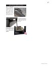
Proceed once the vent installation is complete.
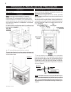
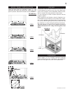
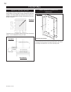
1. Move the fireplace into position and secure using the
nailing tabs and/or secure to the floor through the 1/4"ø
holes located at either end of the base.
2. Route a 3/8" N.P.T. black iron gas line, 1/2" type-L cop-
per tubing or equivalent to the fireplace.
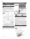
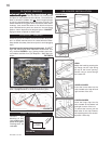
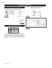
3. For ease of accessibility, an optional remote wall switch
or millivolt thermostat may be installed in a convenient lo-
cation. Route 2-strand (solid core) millivolt wire through
the electrical hole located at the bottom left side of the unit.
The recommended maximum lead length depends on wire
size:
WIRE SIZE MAX. LENGTH
14gauge 100 feet
16gauge 60 feet
18gauge 40 feet
Attach the one lead to terminal 3 (located on the gas valve)
and the other lead to the vent safety switch wire ( located
loose in the valve compartment). See FIGURE 3.
Do not connect either the wall switch, thermostat
or gas valve to electricity (110 volts).
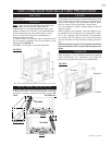
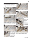
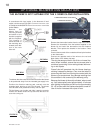
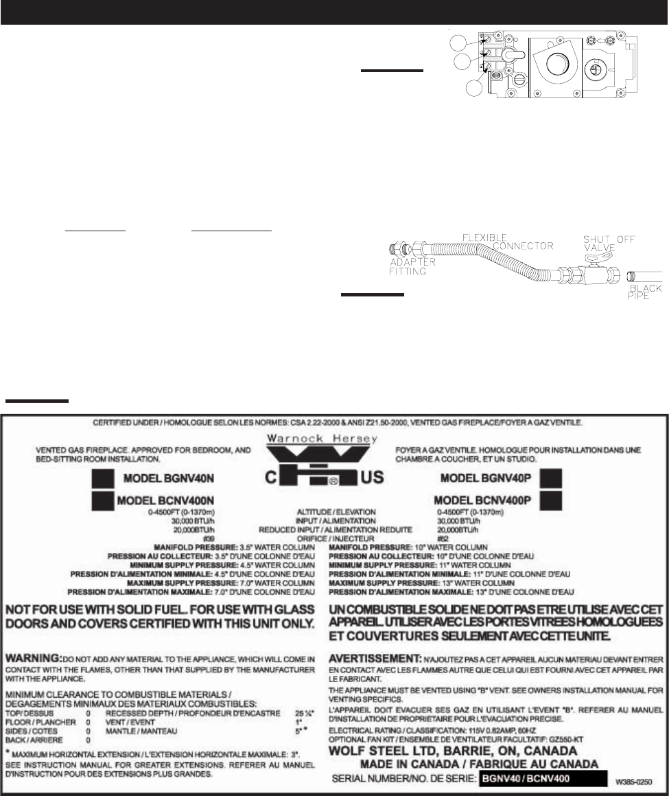
4. Install rigid black pipe, 1/2" type-L copper tubing or, if
local codes permit, a 3/8" flex connector and shutoff valve
to the gas line and the fireplace gas valve. Seal and tighten
securely. An adapter fitting is required between the gas
valve and the copper tubing or flex connector. DO NOT KINK
FLEXIBLE CONNECTOR. FIGURE 6.
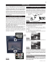
5. Check for gas leaks by brushing on a soap and water
solution.
Do not use open flame.
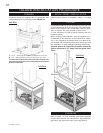
6. Mark the appropriate boxes on the rating plate label to
indicate the model type.
Purge all gas lines with the glass door of the fire-
place open. Assure that a continuous gas flow is
at the burner before closing the door.
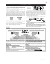
FIGURE 22
P
I
P
I
L
O
T
3
1
2
N
O
L
O
T
H
I
L
O
F
F
O
FIGURE 21
FIGURE 23
GAS INSTALLATION