


W415-0326 / C / 11.23.07
17
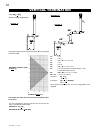
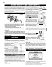
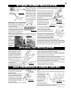
Proceed once the vent installation is complete.
NOTE: All gas connections must be contained within the fi re-
place when complete.
1. Move the fi replace into position and secure to the fl oor through
the 1/4" holes located at either side of the base.
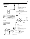
2. The fi replace is designed to accept 3/8" gas supply line. The
fi replace is equipped with a 3/8" manual shut-off valve.
3. Connect the gas supply in accordance to local codes. In the
absence thereof, install according to the National Installation Code.
4. When fl exing any gas line, support the gas valve so that the
lines are not bent or kinked.
5. Check for gas leaks by brushing on a soap and water solu-
tion.
DO NOT USE OPEN FLAME.
Purge all gas lines with the glass door of the stove removed.
Assure that a continuous gas fl ow is at the burner before re-
installing the door.
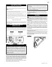
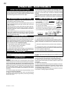
GAS INSTALLATION
Conversion Kits
The mobile home appliance is fi eld convertible between Natural
Gas (NG) and Propane (LP).
To convert from one gas to another consult your Napoleon dealer/
distributor.
Note: In order to avoid the possibility of exposed insulation or
vapour barrier coming in contact with the fi replace body, it is recom-
mended that the walls of the fi replace enclosure be “fi nished” (ie:
drywall/sheetrock), as you would fi nish any other outside wall of a
home. This will ensure that clearance to combustibles is maintained
within the cavity.
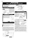
It is best to frame your fi replace after it is positioned and the vent
system is installed. Use 2x4's and frame to local building codes.
It is not necessary to install a hearth extension with this fi replace
system.
When roughing in the fi replace, raise the fi replace to accommodate
for the thickness of the fi nished fl oor materials, i.e. tile, carpeting,
hard wood, which if not planned for will interfere with the opening of
the lower access door and the installation of many decorative fl ash-
ing accessories.
This Mobile/Manufactured Home Listed appliance comes factory
equipped with a means to secure the unit. The fi replace is equipped
with two 1/4” diameter holes located in the front left and right cor-
ners of the base. For mobile home installations, the fi replace must
be fastened in place. Use #10 hex head screws, inserted through
the holes in the base to secure. Always turn off the pilot and the fuel
supply at the source, prior to moving the mobile home.
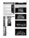
After moving the mobile home and prior to lighting the fi replace,
ensure that the logs are positioned correctly.
MOBILE HOME INSTALLATION
FRAMING
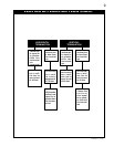
This appliance is certifi ed to be installed as an OEM (Original
Equipment Manufacturer) installation in a manufactured home
or mobile home and must be installed in accordance with the
manufacturer’s instructions and the Manufactured Home Construc-
tion and Safety Standard, Title 24 CFR, Part 3280, in the United
States or the Mobile Home Standard, CAN/CSA Z240 MH Series,
in Canada. This appliance is only for use with the type(s) of gas
indicated on the rating plate. A conversion kit is supplied with the
mobile home appliance.
This appliance is certifi ed to be installed in an aftermarket perma-
nently located, manufactured (mobile) home, where not prohibited
by local codes.
This fi replace is only for use with the type of gas indicated on the
rating plate. This fi replace is not convertible for use with other
gases, unless a certifi ed kit is used.
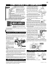
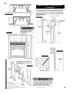
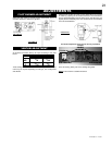
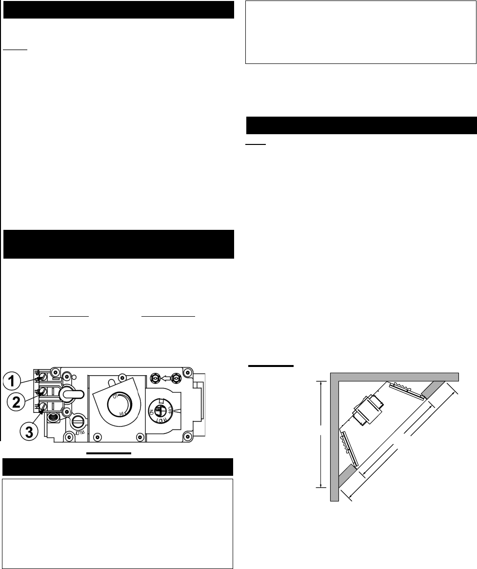
51
1
/2"
48
1
/
2
"
72
11
/
16
"
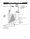
FIGURE 34
Objects placed in front of the fi replace should be kept a minimum of
48" away from the front face.
Combustible materials may be installed fl ush with the front of the
fi replace but must not cover any of the black face areas of the fi re-
place. Non-combustible material (brick, stone or ceramic tile) may
protrude in these areas.
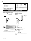
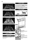
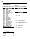
For ease of accessibility, an optional remote wall switch may be
installed in a convenient location. Route 2-strand (solid core) mil-
livolt wire through the electrical hole located at the bottom left side of
the unit. The recommended maximum lead length depends on wire
size:
WIRE SIZE MAX. LENGTH
14 gauge 100 feet
16 gauge 60 feet
18 gauge 40 feet
Attach the two leads to terminals 1 and 3 located on the gas valve.
OPTIONAL WALL SWITCH
INSTALLATION
FIGURE 33