19
W415-0533 / E / 02.09.06
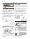
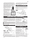
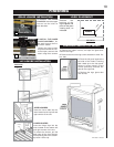
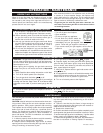
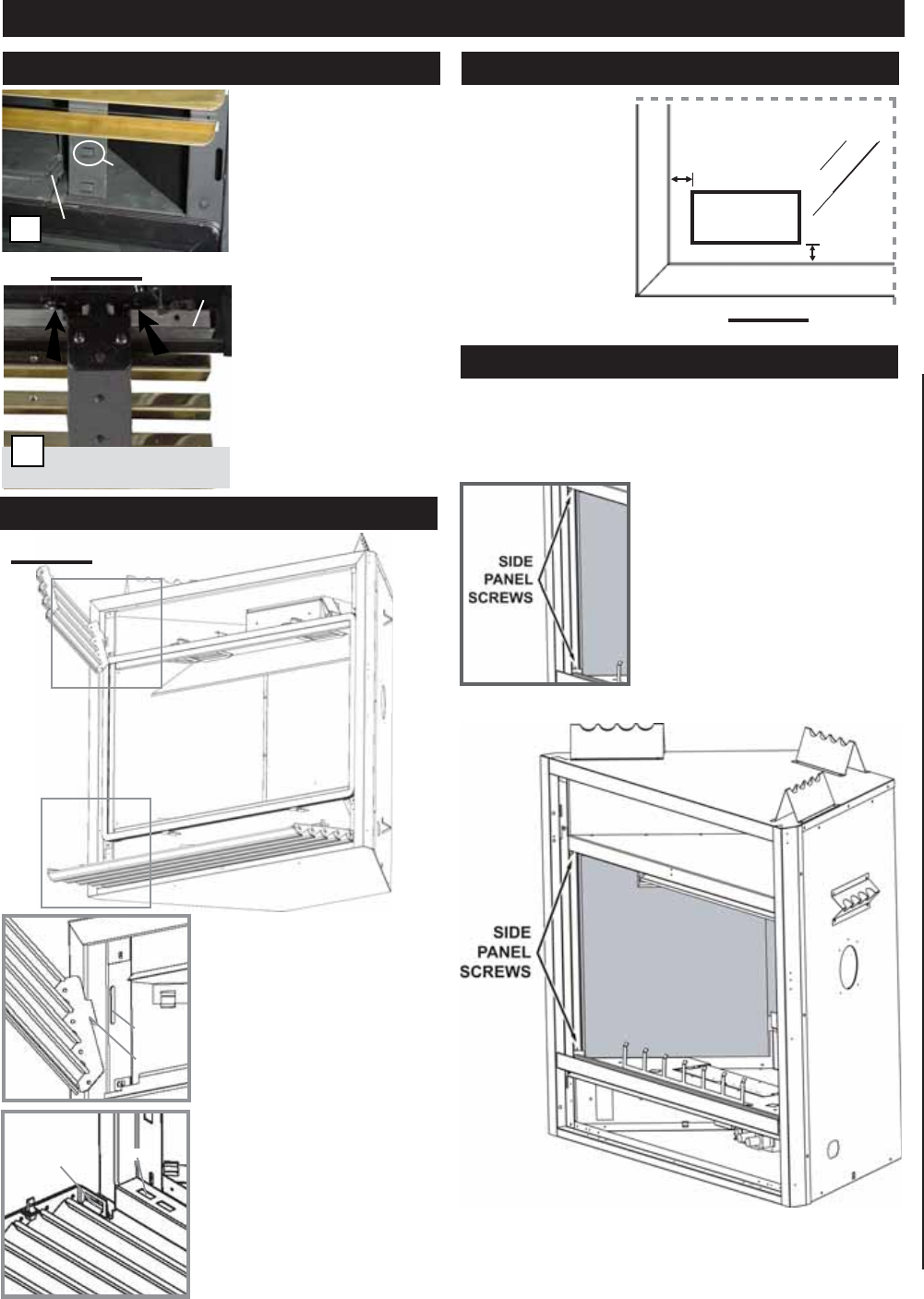
TO INSTALL THE UPPER
LOUVRES: Insert the upper
louvres into the slots on
both brackets.
TO INSTALL THE LOWER
LOUVRE ASSEMBLY: At-
tach each hinge to the fire-
box with 2 screws.
Position the hinge screen
into place and with the con-
trol door open, secure to the
firebox using three screws.
a
DOOR LATCH
UPPER LOUVRE
SLOT
HINGE SCREEN
LOWER LOUVRES
(VALVE CONTROL DOOR)
b
B
A
FIGURE 38
UPPER LOUVRES
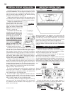
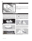
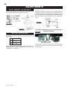
Insert the louvre tabs into the
slots located at the top left and
right corners of the unit.
SLOT
TAB
A
LOWER LOUVRES
Insert the hinge clips into the
slots located at the bottom left
and right corners of the unit.
To remove the louvres, pull the
back tabs of the clips forward,
while pushing the louvre assem-
bly back. Lift the clip.
B
HINGE
CLIP
SLOT
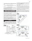
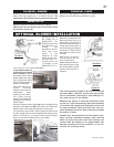
Remove the
backing of the
logo supplied and
place on the glass
viewing door, as
indicated.
FIGURE 39
L42 LOUVRE INSTALLATION
LOGO
½"
½"
FINISHING
GDL42 LOUVRE INSTALLATION
FIGURES 37
LOGO PLACEMENT
PORCELAIN REFLECTIVE PANELS
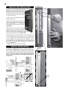
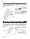
1. Remove the upper louvres, and open the glass door.
Remove the logs.
2. Remove the two securing screws located on either fire-
box side.
3. Place the left panel against the
left side of the firebox, ensuring
that it butts up to the rear panel.
Secure in place using 2 of the
screws previously removed. Re-
peat for the right side.
4. Replace the logs, glass door
and louvres.


