


20
W415-0661 / C / 02.20.08
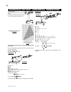
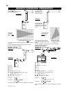
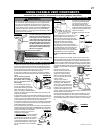
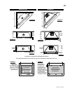
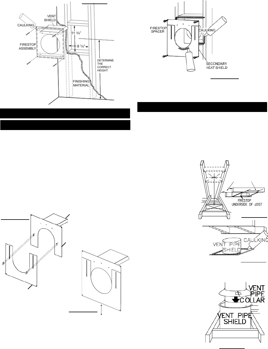
Apply a bead of caulking all around the edge of the opening and
place the fi restop top, so that the vent shield covers the top of the
vent within the opening.
The length of the vent shield may be cut shorter for combustible
walls that are less than 8 1/2" thick but the vent shield must extend
the full depth of the combustible wall.
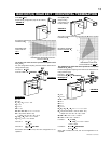
Place the fi restop bottom against the fi restop top and secure the
two together. Adjust the assembly to ensure it is tight to the vent.
Secure fi restop to wall. Ensure that both spacer and shield main-
tain the required clearance to combustibles. Once the vent pipe is
installed in its fi nal position, apply sealant between the vent pipe
and the fi restop spacer. This restricts cold air from being drawn
into the room or around the fi replace. See Figures 49a-c.
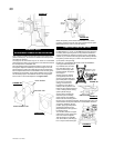
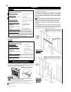
ADJUSTABLE FIRESTOP INSTALLATION
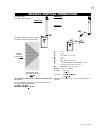
VENT SHIELD
FIRESTOP TOP
FIRESTOP BOTTOM
FIGURE 48
FIGURE 49a
FIGURE 49c
FIGURE 49b
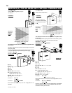
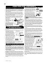
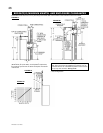
BGD42CF ONLY
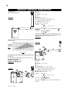
DO NOT FILL THIS SPACE WITH ANY TYPE OF MATERIAL.
A vent pipe shield will prevent
any materials such as insula-
tion, from fi lling up the 1" air
space around the pipe. Nail
headers between the joist for
extra support.
2. Apply a bead of caulking
(not supplied) to the frame-
work or to the Wolf Steel vent
pipe shield plate or equivalent
(in the case of a fi nished
ceiling), and secure over
the opening in the ceiling. A
fi restop must be placed on the
bottom of each framed opening in
a roof or ceiling that the venting
system passes through.
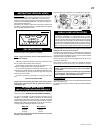
VERTICAL INSTALLATION
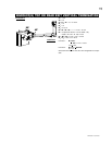
BGD36CF(G) = 9 3/4”
BGD42CF = 10 3/4”
FIGURE 50
FIGURE 51
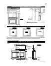
1. Determine the air terminal location, cut and frame 9 3/4" for
the BGD36CF(G), or 10 3/4" for the BGD42CF square opening in
the ceiling and an opening in the roof to provide the minimum 1"
clearance between the fi replace vent pipe and any combustible
material. Try to center the exhaust pipe location midway between
two joists to prevent having to cut them. Use a plumb bob to line
up the center of the openings.
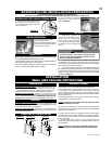
Apply a bead of caulking all
around and place a fi restop
spacer over the vent shield to
restrict cold air from being drawn
into the room or around the fi replace. Ensure that both spacer and
shield maintain the required clearance to combustibles. Once the
vent pipe is installed in its fi nal
position, apply high temperature
sealant W573-0002 (not sup-
plied) between the vent pipe and
the fi restop spacer.
3. In the attic, slide the vent pipe
collar down to cover up the open
end of the shield and tighten.
This will prevent any materials,
such as insulation, from fi lling up
the 1" air space around the pipe.
Where the opening in the outside wall has been cut 13" tall to
provide 2" clearance from the vent pipe, terminal extension plate
W500-0206 must be used to cover the opening.
FIGURE 52