ST2037,47, 47B, 38P, 40T SUB. PUMPS — OPERATION AND PARTS MANUAL — REV. #3 (06/15/10) — PAGE 13
Float Switch
Single
or
dual
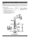
control float switches (Figure 6) can be used for the unattended operation of the submersible pump. When using the
piggy-back power configuration
(plug), the pumps DO NOT require the use of a control box. In this configuration
(piggy-back), the
SW-1 (single float switch) or SW-2 (dual float switch) are required. The illustration below is an example of a single float switch application.
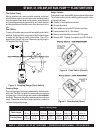
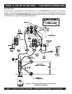
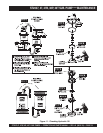
ST2037, 47, 47B, 38P, 40T SUB. PUMP — FLOAT SWITCH (PIGGY-BACK)
Figure 6. Single Float Switch
Application Diagram
Figure 6 shows a
single float
switch
application. For dual float switch
capability use a
Model SW-2
mercury
type float switch .
NOTE
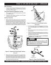
Mounting The Float Switch
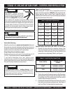
1. Determine the required
cord tether length
as shown in
Figure 6 and Table 3.
2. Place the cord into the clamp as shown in Figure 6.
3. Secure the clamp to the discharge hose as shown in Figure
5. DO NOT install cord under hose clamp.
4. Using a screwdriver, tighten the hose clamp. DO NOT over-
tighten. Make sure the float cord is not allowed to touch the
excess hose clamp band during operation.


