


ST2037,47, 47B, 38P, 40T SUB. PUMPS — OPERATION AND PARTS MANUAL — REV. #3 (06/15/10) — PAGE 17
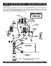
2. Remove the pump AC input connector housing from the
control box, then route the power cord through the cable
gland on the control box.
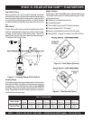
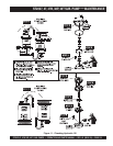
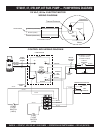
3. Connect the pump power cord to the contactor as shown in
Figure 7 and Table 7.
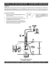
Connecting AC Power to the Control Box
1. The AC power cord (input) should have three wires. Each
wire is color coded. The colors are WHITE, BLACK and
GREEN.
2. Remove the AC input connector housing from the control
box, then route the power cord through the cable gland on
the control box.
3. Connect the AC power cord to the contactor as shown in
Figure 7 and Table 6.
Electrical connections to the power
source should only be performed by
a
licensed electrician
or qualified
personnel.
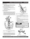
3. Tighten the connector housing to ensure a tight fit between
the power cord and the connector body. This will prevent
the cable from pulling out of the terminal block and also
prevent moisture from entering the control box.
NOTE
4. Connect the other end of the AC power cord to the voltage
source. Remember to provide a means of disconnecting
the power from the control box (circuit breaker or quick
disconnect switch). Also make sure to provide a good earth
ground to the control box.
Connecting AC Power to the Pump
1. AC power is transferred to the pump via a contactor. The
coil of the contactor is energized or de-energized by the
opening and closing of the float switch contacts. The power
cord should have three wires. Each wire is color coded.
The colors are WHITE, BLACK and GREEN.
It is recommended that the power being
supplied to the control box
ALWAYS
be connected to a
circuit breaker
or
a
quick
disconnect
switch. This
safety feature allows for quick removal
of power from the control box in the
event of an emergen
cy.
NOTE
Turning On The Pump
1. If all of the pump's electrical requirements have been met,
place the
circuit
breaker
or power
ON/OFF
switch in the
ON
position.
2. The CB3 control box has an
operation switch
located on
the front cover. This switch has 3 positions, AUTO, MANUAL
and OFF. The AUTO position allows the pump to run in an
un-attended mode. The MANUAL position will let the pump
run without the float switches controlling the pump. When in
the manual mode be careful not to let the pump run dry.
Severe damage to the pump may occur if it is allowed to run
dry. NEVER let the pump
run dry
.
3. Place the operation switch in the AUTO position. The AC
power indicator lamp should be lit (ON).
4. Wait a few seconds and water should begin to flow from the
discharge hose.
5. If water is not flowing from the discharge hose or not flowing
freely after a few minutes, remove the power from the pump
and check the system for leaks.
6. To stop the pump from pumping, place the operation switch
in the OFF position.
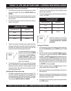
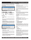
REWOPTUPNICA.6ELBAT
ROTCATNOCOTSNOITCENNOC S
ROLOCERIWELBACROTCATNOC
KCALB1L
ETIHW2L
NEERGDNUORG
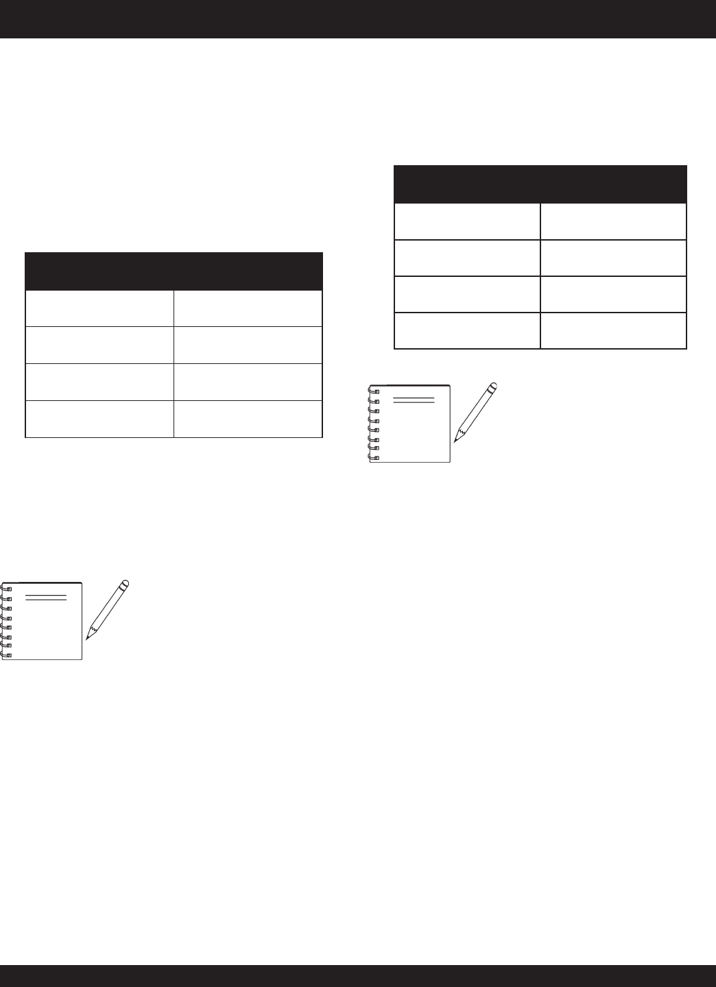
REWOPTUPTUOCA.7ELBAT
PMUPOTSNOITCENNOC
ROLOCERIWELBACROTCATNOC
KCALB1T
ETIHW2T
NEERGDNUORG
ST2037, 47, 47B, 38P, 40T SUB. PUMP
—
CONTROL BOX INSTALLATION