PAGE 20 — MQD2H/3H DIAPHRAGM PUMPS — OPERATION AND PARTS MANUAL — REV. #6 (10/27/11)
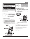
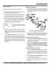
To perform the pump vacuum test do the following:
1. Start the engine as outlined in the initial start-up section,
and wait for the pump to begin pumping.
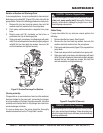
2 Check and make sure that there are no air leaks between
the vacuum tester (Figure 21) and the inlet port on the
pump. If air leaks are present reseat vacuum tester.
3. Run the pump for a few minutes while monitoring the
vacuum gauge. If the gauge indicates a reading between
-25 and -20 in. Hg. (inches of mercury) then it can be
assumed that the pump is working correctly.
Pump Vacuum Test
22 in. Hg (inches of mercury)
translates into 25 feet of lift at
sea
level
.
4. If the vacuum tester gauge indicates a reading
below
-20 in. Hg, it can then be assumed that the pump
is not functioning correctly, and corrective action needs
to be taken.
5. To test the
flapper valve
, shut down the engine. The
vacuum tester should remain attached to the pump
suction inlet port by vacuum. This indicates the pump's
flapper valve is seating properly to hold water in the
suction hose when the engine is stopped. This prevents
backflow and allows for faster priming when the engine
is restarted.
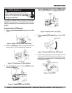
Gear Reduction Oil (Transmission)
1. Check gearbox oil level every
20 hours
of operation or
at least once a week; more often if any leakage is
detected around the gearbox.
2. Change transmission oil after the first
40 hours
of
operation. Use SAE 80/90
EP (API GL-5) gear oil.
Transmission oil capacity is 22 ounces (651 ml.). Check
oil level periodically and change oil after every
350 hours
of operation.
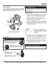
Connecting Rod Bearing Lubrication
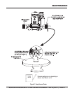
1. Grease connecting rod bearing (Figure 8) every
8 hours of operation.This is done by rotating the
rod bearing to the 12 o'clock position. At this point
the grease fitting will be visible through the guard
hole.
2. Use only
premium lithium based grease
, conforming
to NLG1 Grade #2 consistency.
3. Remove connecting rod guard occasionally and
wipe up excess grease from connecting rod
bearing.
NOTE
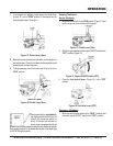
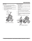
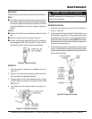
Flapper Valve Replacement
1. Remove the two bolts that secure the suction port
chamber (Figure 20) to the pump well. Remove suction
port chamber. Replace valves as required and
reassemble.
Figure 20. Flapper Valve Replacement
2. Remove the two bolts that secure the discharge port
(Figure 20) to the pump well. Remove discharge port
plate.Replace valves as required and reassemble.
MAINTENANCE


