


Operating Instructions and Owner’s ManualCompact Unit / Utility Heater
E-9
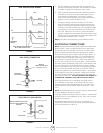
5. Test for spillage at the draft hood relief opening after five
minutes of main burner operation. Use the flame of a match
or candle, or smoke from a cigarette, cigar, or pipe.
6. After it has been determined that each appliance remaining
connected to the common venting system properly vents
when tested as outlined above, return doors, windows,
exhaust fans, fireplace dampers and any other gas-burning
appliance to their previous condition of use.
7. If improper venting is observed during any of the above
tests, the common venting system must be corrected. The
common venting system should be resized to approach the
minimum size as determined by using the appropriate tables
in Appendix G in the current standards of the National Fuel
Gas Code, ANSI Z223-1 in the U.S.A. and the appropriate
Category I Natural Gas and Propane appliances venting sizing
tables in the current standards of the CSA B149.1 Natural Gas
and Propane Installation Code in Canada.
NOTE Local codes may supersede any of the above provisions.
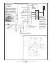
ELECTRICAL CONNECTIONS
NOTE The MHU series unit heaters use a direct spark ignition
system. There is no pilot necessary as the spark lights the
main burner as the gas valve is turned on. The direct spark
N
MANUAL
MAIN SHUT-OFF VALVE
(FURNISHED BY INSTALLER)
GAS SUPPLY CONNECTION
GAS FLOW
DRIP LEG
GROUNDED
JOINT UNION
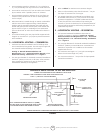
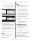
LINE VOLTAGE FIELD WIRING
UNIT
BLACK
BLACK
WHITE
WHITE
EQUIPMENT
GROUND
BLACK WIRE WITH WHITE TAPE OR
WHITE WIRE WITHOUT TAPE
L1
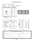
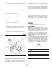
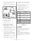
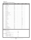
FIGURE 7
GAS SUPPLY TO UNIT HEATER
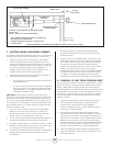
ISOLATE
GAS VALVE
MANUAL MAIN SHUT-OFF VALVE
WILL NOT HOLD NORMAL TEST
PRESSURE
CAP
UNIT HEATER
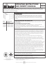
FIGURE 8
FIGURE 9
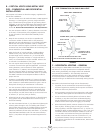
NOTE: The MHU/HSU series unit/utility heaters use a direct spark
ignition system. There is no pilot necessary as the spark lights
the main burner as the gas valve is turned on. The direct spark
ignition control board emits radio noise during burner ignition.
The level of energy may be enough to disturb a logic circuit in a
microprocessor controlled thermostat. It is recommended that
an isolation relay be used when connecting the unit heater to a
microprocessor controlled thermostat. Select circuit protection
and wire size according to the unit rating plate. Install a separate
disconnect switch (protected by either fuse or circuit breaker) near
the unit so that power can be turned off for servicing. Remove
electrical junction box cover and connect wiring through knockout
on the junction box located on the side of the heater. Refer to
heater wiring diagram for connection information. Use 18 gauge
wire or larger for line power connections. Make sure to connect
line power to wires located in the external electrical junction box
behind junction box cover. DO NOT CONNECT LINE POWER TO
THERMOSTAT TERMINAL STRIP ON OUTSIDE OF HEATER.
Electrically ground the unit in accordance with local codes or
in the absence of local codes, in accordance with the current
National Electrical Code (ANSI/NFPA No. 70) in the USA, and in
Canada with the current Canadian Electrical Code, Part 1 CSA
C22.1
NOTE: Un-insulated ground wire must be warped in electrical tape
to avoid damage to the electrical system.
Make line voltage connections as shown in figure 7. Connect field
wiring as shown on wiring diagram on unit. Also, refer to typical
diagram in this manual.
An additional thermostat wire must be run to terminal g on
heater when continuous blower is desired. Thermostat (optional).
See wiring schematic on pager E-13.