


E6
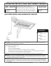
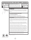
Installation instructions and Owner’s Manual
Model # MH25NG/LP HS25NG/LP
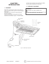
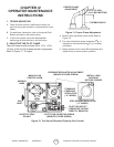
• This heater may be mounted on any wall;
however, it is recommended that the heater be
mounted in the middle of the wall opposite any
overhead doors.
• When selecting installation locations for this
heater ensure that the opening of any exterior
or interior doors or windows will not violate
minimum clearances or contact any heater
components.
• If an overhead door is installed in the build-
ing, verify that the heater is not installed in
such a way as to interfere with door operation
and verify that the door in its open position
will not reduce clearances below the minimum
requirements. Never mount the heater in such
a way that would position the heater above an
opened overhead door.
• In most cases the inltration around your unin-
sulated entry doors and windows will provide
enough air ow for efcient heater operation.
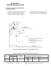
Unrestricted air ow during heater operation is essen-
tial to prevent the area above the installed heater from
overheating. If your workshop/utility building is tightly
insulated (including windows, doors, openings, etc.) the
following ventilating methods must be followed:
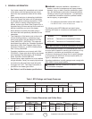
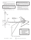
• A single exhaust vent is supplied with your
heater for your convenience. This vent must
be located above the heater (preferably at the
highest point in the building interior) and it must
vent to the exterior of the building. An addition-
al vent is available from the factory for those
having a nished workshop or utility building.
• An intake vent, or equivalent, from the exterior
of the building and having an effective area of
75 square inches must be located below the
heater (preferably within 2 feet of the building’s
oor).
• Openings equivalent to intake vent would be:
partially open doors and partially open win-
dows.
• Openings of this size (5 inch by 13 inch, or 3
inch by 25 inch) will prevent dangerous heat
buildup above the heater.
Ensure that no gas lines or electrical wiring or conduits
will interfere with mounting of the heater to the wall.
Depending on local codes and requirements and the
installer’s skill level, the sizing and installation of gas
lines required to supply the heater may require the
assistance of a professional. If in doubt as to these
requirements, discuss the requirements of this manual
with the dealer from whom the heater was purchased
and your gas supplier, or call our customer service
department at 1-800-251-0001.
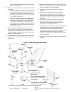
The selection of the thermostat mounting location is
critical to efcient and effective heater operation.
• The thermostat should be mounted about 5 feet
above the oor where air can circulate freely
around it.
• The thermostat should not be mounted directly
to a cold exterior wall without an insulated
mounting block.
• The thermostat should not be mounted in direct
drafts.
• The thermostat should not be mounted directly
below the installed the heater.
• The thermostat should not be installed at a
distance that is farther from the heater than the
length of the thermostat cable.
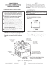
2. HEATER MOUNTING INSTRUCTIONS
After selecting the heater installation location and the
thermostat location and after verifying and ensuring that
all of the above placement requirements are fullled,
mount the heater as follows:
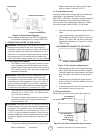
A. Determine how you wish to install the vent based
on the construction of the building and your
personal preference. (i.e., do you wish the anged
(nished) side on the interior or the exterior of the
building or do you want two vents so that both
exterior and interior will be nished?) If needed,
order an additional vent from the factory. Our
address and toll free phone number are on the rear
cover of this manual. Install the vent as follows:
1. See Figure 3 for dimensions and information on
the vent.
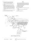
2. Select a place as high above the heater as
possible in accordance with the above require-
ments and ensure that the vent or vents will
not contact or interfere with existing building
systems (i.e., ducts, wiring, plumbing, etc.)
3. Place the unnished side of the vent against
the wall in its elected location and trace its
dimensions on the wall with a pencil or other
suitable marker.
4. Cut or otherwise open a hole in the wall, or
walls for nished buildings, having the dimen-
sions of the unnished side of the vent.
5. Install the vent or vents as desired and retain