


E7
Installation instructions and Owner’s Manual
Model # MH25NG/LP HS25NG/LP
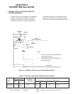
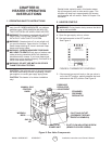
with 4 suitable fasteners through the predrilled
holes in vent ange.
B. Prepare to install the heater wall mounting bracket
as follows:
1. If the wall mounting bracket is to be attached to
a stud and wallboard wall, refer to Figure 3 for
dimensions, locate a stud, and drill two 1/8” pi-
lot holes into the stud centerline. Use template
for simplied installation.
2. If the wall mounting bracket is to be attached
to a brick or masonry wall, refer to Figure 3 for
dimensions. Obtain two 1/4 inch (inside diam-
eter) expansion anchors and determine the
correct drill size to be used with them. Drill the
appropriate size holes in the brick or masonry
to accept the anchors.
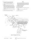
C. Place the wall mounting bracket on the wall and
align the two through holes on the bracket with
the pilot holes or anchors. Install 1/4 inch by 2-1/2
inch lag screws through the bracket into the stud or
anchors. Tighten securely.
D. Locate heater mounting clip on back of heater and
select the 1/4” – 20 by 3/4” hex head bolt and 1/4” -
20 hex nut.
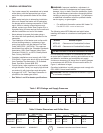
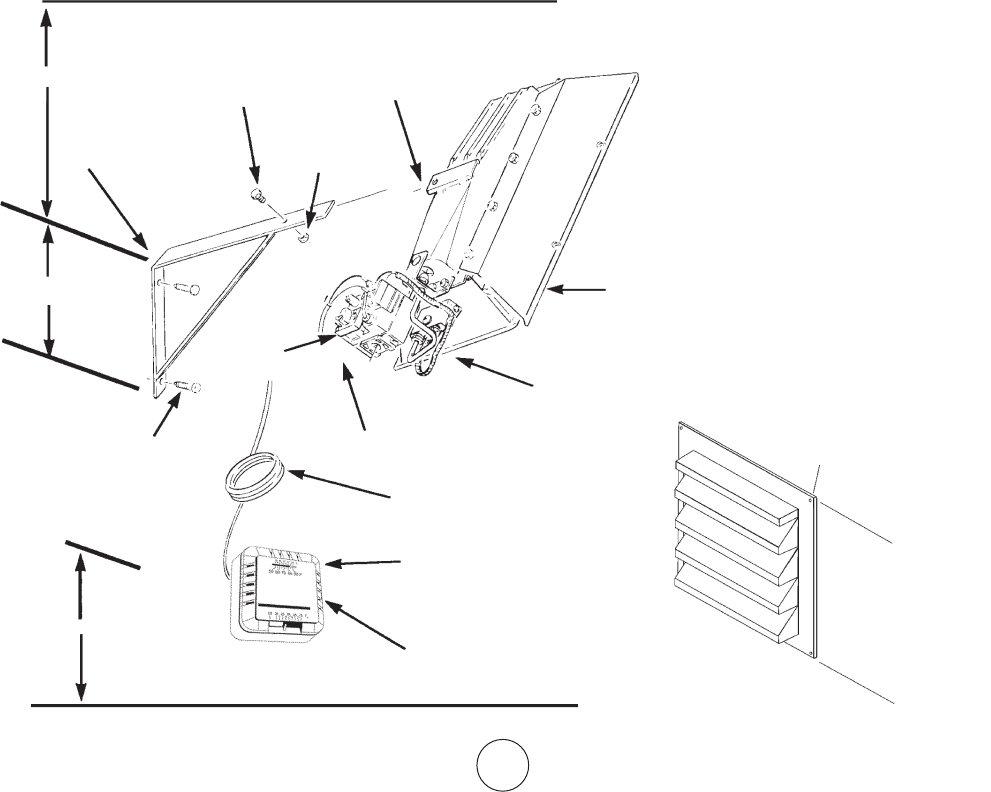
CEILING
HEATER
24” MIN
9”
58”
FLOOR
THERMOSTAT (SEE INSTRUCTIONS
INCLUDED WITH THERMOSTAT
#6 X 1” SHEET METAL SCREWS
(2 REQUIRED - INCLUDED WITH
THERMOSTAT)
THERMOSTAT CABLE
(SEE FIGURE 4)
1/4” X 2-1/2” LONG
LAG SCREWS
(2 REQUIRED)
GAS
CONTROL
VALVE
1/2” NPT GAS INLET
(DO NOT EXCEED 1/2 PSI)
HEATER RE-
FLECTOR
FLUE DE-
FLECTOR
1/4”-20x3/4” HEX-
HEAD BOLT
MOUNTING
CLIP
1/4”-20
HEX NUT
HEATER WALL
MOUNTING
BRACKET
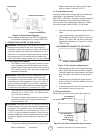
PREDRILLED
HOLES
FINISHED
SIDE
UNFINISHED
SIDE
FLANGE
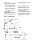
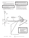
E. Position the heater as shown in Figure 3 and slide
the heater mounting clip over the bracket and install
the bolt through the clip and bracket.
F. Thread the hex nut onto the bolt and tighten
securely.
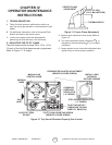
G. Ensure that the selected thermostat location
meets all of the above requirements. Refer to
the instructions that come with the thermostat for
additional grounding information and mounting
instruction.
H. If the wall is of stud and wallboard construction,
then use the #6 by 1 inch sheet metal screws,
included with the thermostat, and mount the
thermostat in the selected location.
I. If wall is brick or masonry, the appropriate anchors
must be obtained to accommodate thermostat
mounting screws. Use the back plate of the
thermostat as a template to mark the hole locations,
drill appropriate size anchor holes, install the
anchors, securely attach the thermostat using the
mounting screws.
J. Connect thermostat wires to gas valve as shown in
Figure 4.
Figure 3. Heater Mounting Information