


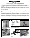
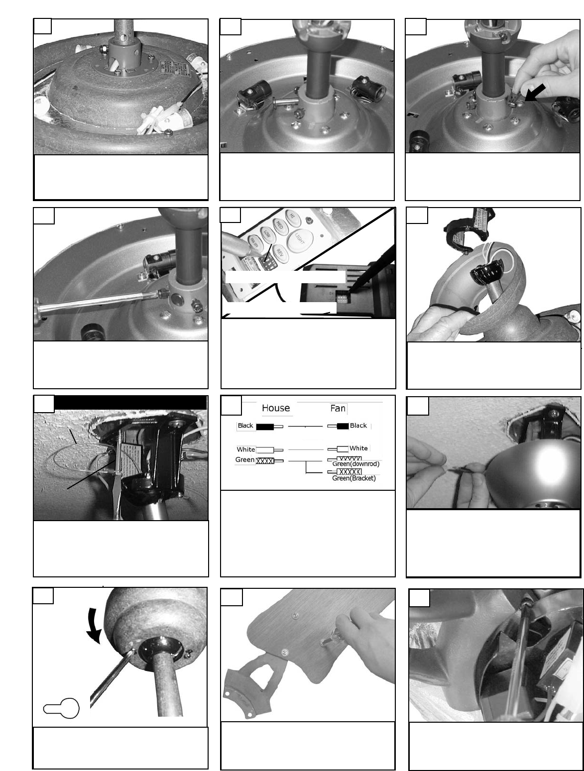
i
nstall cotter pin into cross pin.
I
nstall downrod into yoke.
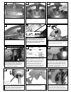
Raise fan with downrod assembled to the ceil-
ing bracket and hang fan assembly. Be sure to
rotate the downrod ball so that the notch in the
bracket engages the slot in the ball.
9
12
7
F
or Canadian installation in both flush and
downrod mode the safety cable must be
installed into the house structure beams using
the 3” lag screws provided. Make sure that
when the safety cable is fully extended the
leadwires are longer than the cable and no
stress is placed on the leadwires.
13
Canadian mounting only
Safety Cable
Lag Screw
Make wire connections to power source using
wire nuts provided. Make sure that no filiments
are outside of the wirenut. After making the
wire connections, the wires should be spread
apart with the grounded conductor and the
equipment-grounding conductor on one side of
the outlet box and ungrounded conductor on
the other side of the outlet bo
x.
15
Attach blade brackets to blades using the blade
br
ack
et screws and w
ashers pro
vided.
17
Check the motor for plastic shipping stabiliz
er
tabs, and remove them if they are present. The
screws, washers and motor pads are pre-
installed to the blade holders. A
ttach blade
assembly to motor and tighten screws securely.
18
Make wire connections as per above diagram.
Connect the white wire from the fan to the
White or Neutr
al wire from the power source.
Connect the black wire from the fan to the
Black or hot wire from the power source.
Connect all Green / Y
ellow wires from the fan,
Downrod and mounting bracket to the
Grounding wire from the house.After wire nuts
are installed push connections carefully into
outlet box with wire nuts pointing upward.
14
S
et dip switches on the Remote Transmitter and Remote
R
eceiver to the same settings. This must be done so the
u
nits will communcate properly. If yo
u have other fans you
can set to control from one transmitter by setting both
receivers the same as the transmitter. If you have more
than one fan with remote. You can set the dip switches to
different positiosns to have seperate control.
Remote Transmitter Dip swtiches
Remote Receiver Dip switches
11
Lift Canopy to ceiling aligning the key hole slots
with the screws on the bottom of the Mounting
bracket. Rotate the canopy Counter Clockwise
to lock in place. Tighten the screws to secure
the Canopy. See inset for Keyhole shape
16
A
lign hole in downrod with hole in yoke and
i
nstall cross pin.
8
Tighten 2 downrod set screws.
10