


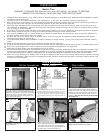
Hang fan from mounting br
ack
et by
the hands free hook into a closed
hole on the edge of the Canopy.
Note: For Canadian mounting refer to
Step #8.
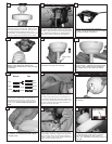
For Canadian installation in both flush and down-
r
od mode the safety cable must be installed into
the house structure beams using the 3” lag screws
provided. Make sure that when the safety cable is
fully extended the leadwires are longer than the
cable and no stress is placed on the leadwires.
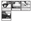
Remove all 4 screws from Mounting
bracket. These screws will not be needed
for Downrod Mode installation
Hang assembled fan from the mounting bracket
i
nstalled to ceiling in previous step. Make sure the
f
an is hanging straight. Rotate fan until the tab on
the Mounting bracket engages the slot on the
Downrod Ball. This must be done to prevent the fan
b
ody from rotating when the blades are in motion.
Place canopy on top of the fan motor allowing the
yoke to pass through the large hole in the center
of the canopy. Align the 3 larger holes around the
center hole with the 3 screws already installed in
the fan. Install 3 flush mount screws pro
vided into
smaller holes and tighten securely.
7
8
9
17
18
Canopy
Center
Hole
Larger
holes
Smaller
holes
Hands free hook
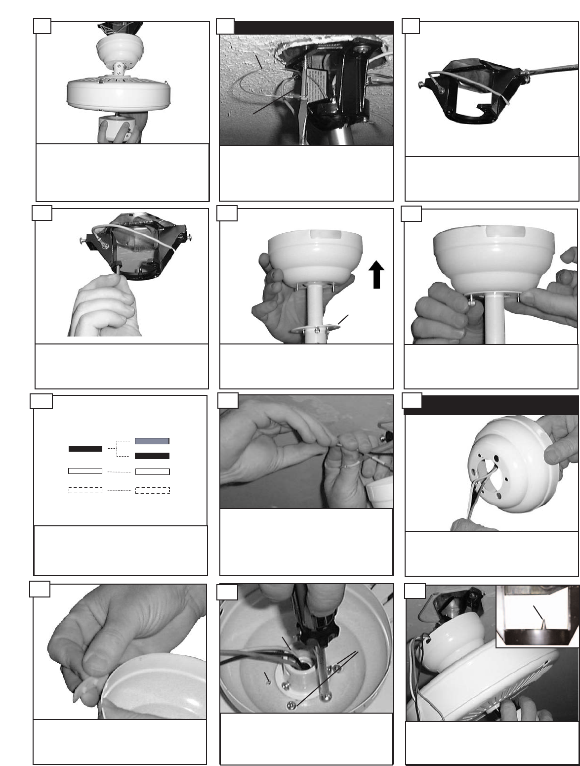
Make wire connections to power source using wire nuts
provided. Make sure that no filiments are outside of
the wirenut. After making the wire connections, the
wires should be spread apart with the grounded con-
ductor and the equipment-grounding conductor on one
side of the outlet box and ungrounded conductor on
the other side of the outlet box.
CCaannaaddiiaann mmoouunnttiinngg oonnllyy
Safety Cable
Lag Screw
14
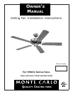
Make sure the studs protruding from the
bottom of the Mounting bracket are
installed with threads all the way through
the bracket.
10
Pass leadwires and safety cable through
the canop
y
.
Remove side covers from canopy expos-
ing 4 holes. 2 closed holes and 2 open
“L” shape holes.
16
FFlluusshh MMoouunntt IInnssttaallllaattiioonn
15
Lift Conopy allowing the 2 studs to
protrude through the canopy.
11
Next lift the cover ring and install knurled
nuts as shown. Tighten the knurled nuts
securely. The canopy should adjust for
any irregularity in the ceiling or Outlet
box.
12
Connect black and blue wire from fan to Black or (Hot)
wire from house. Connect White wire from Fan to
White (Neutr
al) wire from house. Connect Ground
leads from mounting br
ack
et and downrod to Ground
lead from house.
Refer to Safety Tips section of
manual.
13
Cover Ring
House
Fan
Blue
Black
White
Green
Black
White
Ground