


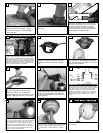

R
aise fan with downrod assembled to
the ceiling brack
et and hang fan
assembly
. Be sure to rotate the
downrod ball so that the notch in the
brack
et engages the slot in the ball.
13
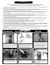
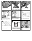
Align hole in downrod with hole in
yoke and install cross pin. Install
d
ownrod into yoke. Install keeper
into cross pin.
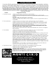
7
Tighten 2 downrod set screws and
lock nuts.
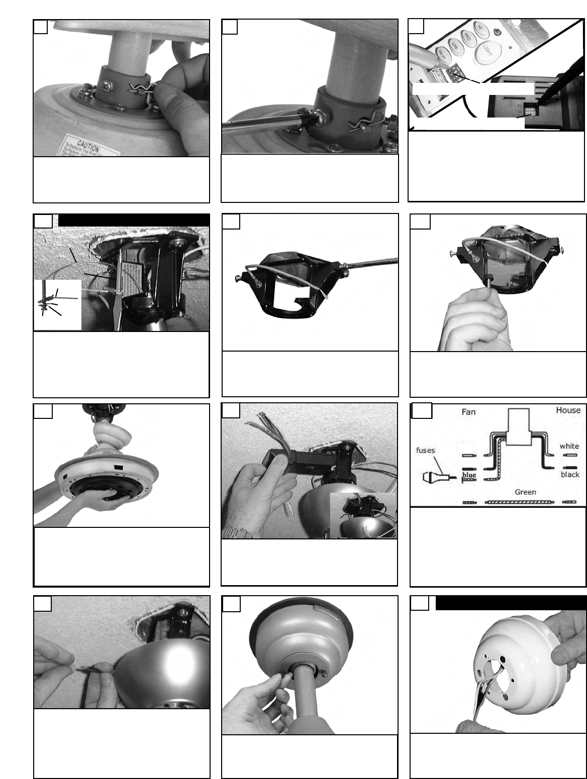
8
S
et dip switches on the Remote Transmitter and Remote
Receiver to the same settings. This must be done so the
units will communcate properly. If you have other fans you
c
an set to control from one transmitter by setting both
r
eceivers the same as the transmitter. If you have more
than one fan with remote. You can set the dip switches to
different positiosns to have seperate control.
R
emote Transmitter Dip swtiches
R
emote Receiver Dip switches
9
Install remote receiver by sliding into opening in
the Mounting br
acket. Make sure that the dip
switches on the T
r
ansmitter and the Receiver
are set to the same position. See Fig 38 for
remote operation
14
Fan and light kit combinations over 35 lbs,
in both flush and downrod mode the safety
cable must be installed into the house struc-
ture beams using the 3” lag screws,washers,
and lock w
ashers. pro
vided. Mak
e sure that
when the safety cable is fully extended the
lead wires are longer than the cable and no
stress is placed on the lead wires.
10
Safety cable installation
S
afety Cable
Lag Screw
s
afety
cable
3
” lag
screw
l
ock
washer
washer
Remove all 4 screws from Mounting
bracket. These screws will not be
needed for Downrod Mode installa-
tion
11
Make sure the studs protruding from
the bottom of the Mounting bracket
are installed with threads all the way
through the bracket.
12
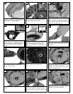
Make wiring connections as indicated above.
White from fan to white from remote mark
ed
N. Blue from fan to blue from remote marked
light. Black from fan to Black from remote
marked L. White from house to white from
remote mark
ed AC N . Black from house to
Black from remote marked AC L. Connect all
green ground wires to Ground wire from
House.
white
black
15
Make wire connections to power source using
wire nuts pro
vided. Mak
e sure that no filiments
are outside of the wirenut. After making the
wire connections, the wires should be spread
apart with the grounded conductor and the
equipment-grounding conductor on one side of
the outlet box and ungrounded conductor on
the other side of the outlet bo
x.
16
Next lift the cover ring and install knurled
nuts as shown. Tighten the knurled nuts
securely. The canopy should adjust for
any irregularity in the ceiling or Outlet
bo
x.
17
Pass leadwires and safety cable through
the canopy.
18
FFlluusshh MMoouunntt IInnssttaallllaattiioonn