


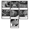
Hang assembled fan from the mounting bracket
installed to ceiling in previous step. Make sure the
f
an is hanging straight. Rotate fan until the tab on
the Mounting bracket engages the slot on the
Downrod Ball. This must be done to prevent the fan
b
ody from rotating when the blades are in motion.
11
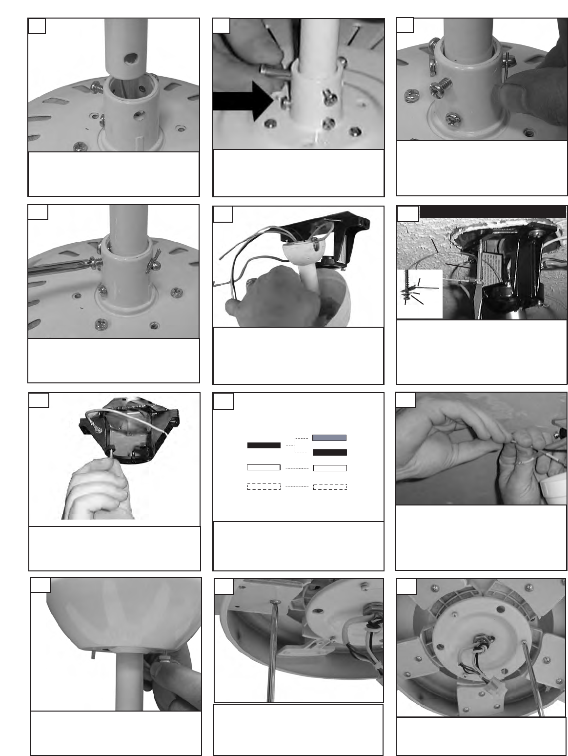
Make wire connections to power source using wire nuts
provided. Make sure that no filiments are outside of
the wirenut. After making the wire connections, the
wires should be spread apart with the grounded con-
ductor and the equipment-grounding conductor on one
side of the outlet box and ungrounded conductor on
the other side of the outlet box.
15
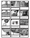
Make sure the studs protruding from the
bottom of the Mounting bracket are
installed with threads all the way through
the bracket.
13
Lift canopy and install knurled nuts as
shown. Tighten the knurled nuts securely.
The canopy should adjust for any irregu-
larit
y in the ceiling or Outlet box.
16
Connect black and blue wire from fan to Black or (Hot)
wire from house. Connect White wire from F
an to
White (Neutral) wire from house. Connect Ground
leads from mounting bracket and downrod to Ground
lead from house.
Refer to Safety Tips section of
manual.
14
House
Fan
Blue
Black
White
Green
Black
White
Ground
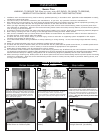
Place downrod into fan yoke.
7
Install the keeper to pin.
9
Tighten the 2 set screws on the yoke
once the downrod is in place.
10
A
lign the hole in the Downrod with the hole in
the Yoke. Insert the Pin through the Yoke and
Downrod until the point appears on the other
side.
8
Check the motor for shipping stabi-
lizers and remove if present. Attach
blades using screws and washers in
hardware pak. Tighten screws
securely.
17
Loosen 2 screws and remove 1 screw
from motor plate. Save removed
screw for use later.
18
Fan and light kit combinations over 35 lbs,
in both flush and downrod mode the safety
cable must be installed into the house struc-
ture beams using the 3” lag screws,washers,
and lock washers. provided. Make sure that
when the safety cable is fully extended the
lead wires are longer than the cable and no
stress is placed on the lead wires.
12
Safety cable installation
S
afety Cable
Lag Screw
safety
c
able
3
” lag
screw
l
ock
w
asher
washer