


18 75D2523
Maximum
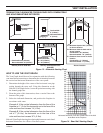
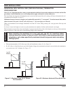
20"
10
1
/2"
(267mm)
10
1
/2"
(267mm)
8
1
/2"
(216mm)
Combustible
Wall
Noncombustible
Wall
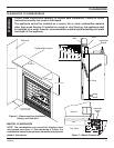
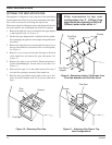
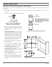
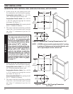
REAR WALL VENT INSTALLATION (5"X8" VENTING ONLY)
When installed as a rear vent unit this appliance may be vented directly to a termination located on the rear wall behind
the appliance
• The maximum horizontal distance between the rear of the appliance and the termination is 20" (508 m). See
Figure 15.
• Only one 45° elbow is allowed in these installations.
VENTING INSTALLATION
Figure 15 - Rear Vent Application,
Maximum Horizontal Distance
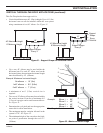
Top View Flat Installation
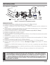
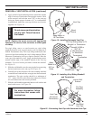
1. Rigid vent pipes and fittings have special
twist-lock connections. Assemble the desired
combination of pipe and elbows to the appli-
ance adaptor.
Twist-lock Procedure: The female ends
of the pipes and fittings have three locking
lugs (indentations). These lugs will slide
straight into matching slots on the male end of
adjacent pipes and fittings. Push the pipe sec-
tions together and twist one section clockwise
approximately one-quarter turn until the sec-
tions are fully locked. See Figure 16.
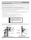
2. See venting and termination instructions for
further instructions.
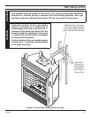
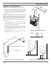
3. Locate and cut the vent opening in the wall.
For combustible walls first frame in opening.
Combustible Interior Walls: Cut a 12
1
/2"H x
10
1
/2" W hole through the interior wall.
Combustible Exterior Walls: Cut a 10
1
/2"H
x 10
1
/2"W square hole through the exterior
wall frame. See Figure 17.
Noncombustible Walls: Hole opening should
be 8
1
/2" (216mm) in diameter.
4. The center of the hole should line up with the
center line of the horizontal rigid vent pipe
end. Allow
1
/4" minimum rise per foot. See
Figure 17.
Note: Horizontal runs of vent
must be supported every three
feet (914mm). Use wall straps
for this purpose.
Figure 16 - Rigid Vent Pipe Connections
Female
Locking Lugs
Male Slots
Figure 17 - Exterior Wall Framing Dimensions